Wendy & Sarah
Process documentation
We first come up with an idea. Since Arduino is basically an environment that transforms in-between inputs and outputs, in the form of lights/sounds, we decide to make something LEDed.
Here is the car prototype we made with scrap cardboard.
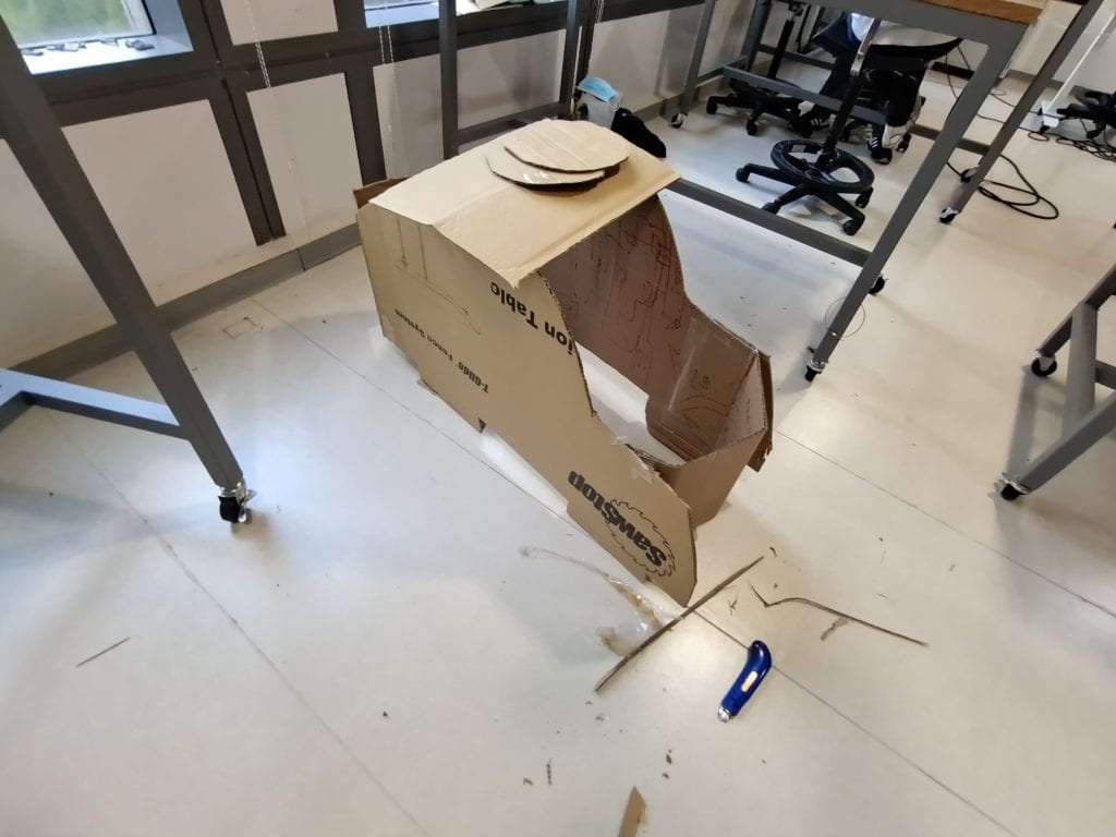
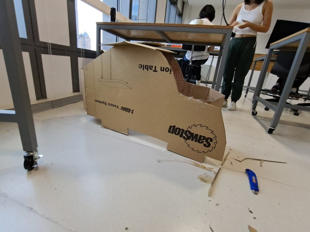
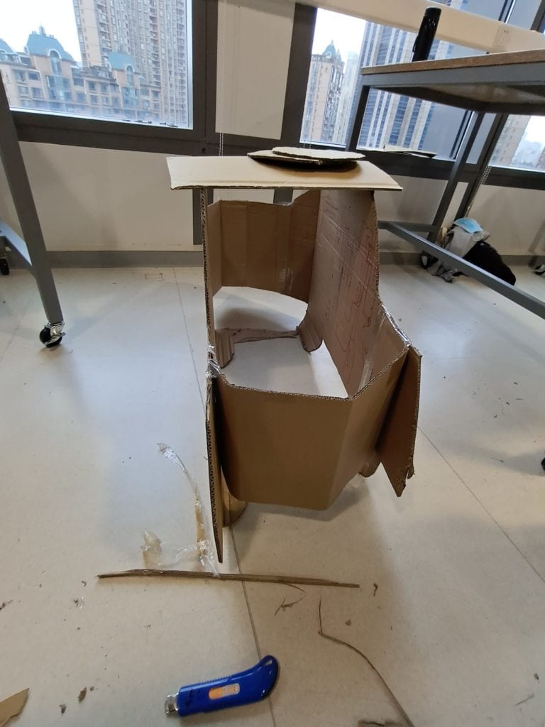
We made it a base and planned to tie LED stripes onto it; while also “wearable” during presentation!
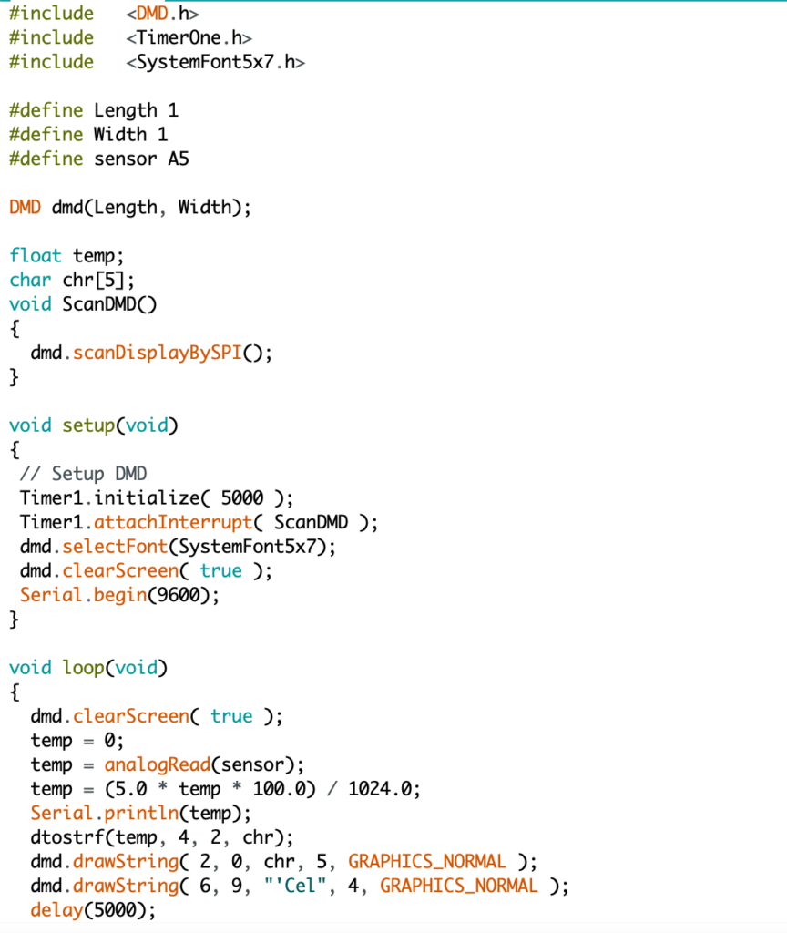
Here’s the code!
/* Insert file library */
#include <SPI.h> #include <DMD.h> #include <TimerOne.h> #include <SystemFont5x7.h> #define Panjang 1 // Number of length of Display P10 #define Lebar 1 // Number of width of Display P10 #define sensor A5 // Define sensor pin = pin A5
DMD dmd(Panjang, Lebar); // Length x Width /* Deklarasi Variable */ float suhu; char chr[5]; void ScanDMD() { dmd.scanDisplayBySPI(); } void setup(void) { // Setup DMD Timer1.initialize( 5000 ); Timer1.attachInterrupt( ScanDMD ); dmd.selectFont(SystemFont5x7); // Font used dmd.clearScreen( true ); Serial.begin(9600); // Activate function of communication serial } void loop(void) { dmd.clearScreen( true ); suhu = 0; suhu = analogRead(sensor); suhu = (5.0 * suhu * 100.0) / 1024.0; Serial.println(suhu); dtostrf(suhu, 4, 2, chr); dmd.drawString( 2, 0, chr, 5, GRAPHICS_NORMAL ); dmd.drawString( 6, 9, “‘Cel”, 4, GRAPHICS_NORMAL ); delay(5000); }
Also attached a photo:
The Poster
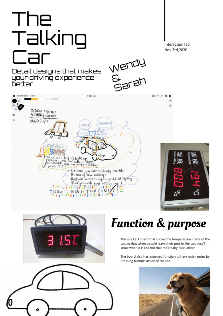
Result
Unfortunately, this project did not turn out well. The code was correct, yet the board displays unreadable patterns. We think that the board is broken. This is a pity and we will try prepare for material a lot earlier, and also not order online given that we have supply in our equipment room.
