Playful Robots Part One
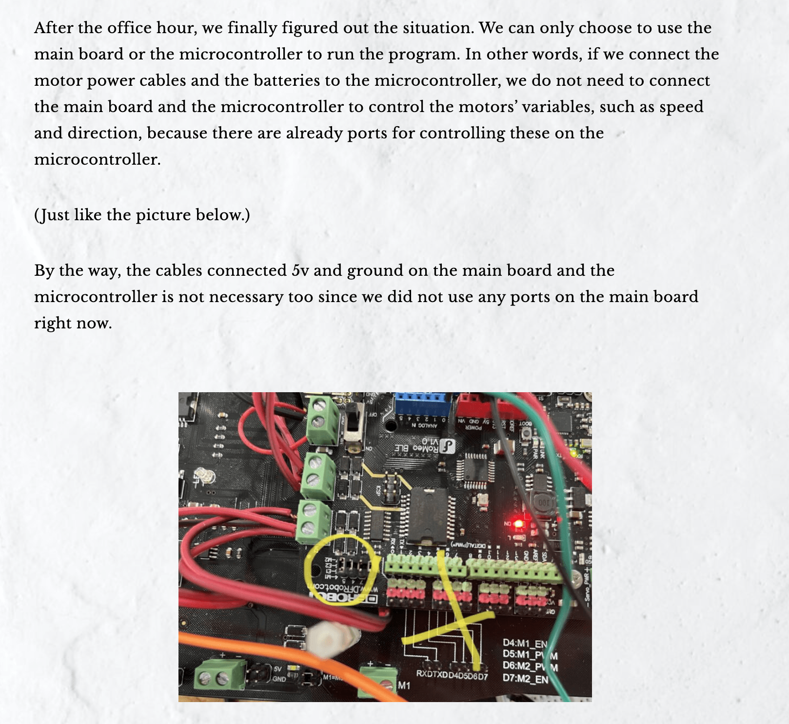
The most correct decision for this part is to change almost all the circuits on the main board to the microcontroller. We used to alter the speed difference to rotate the car. For example, left wheel: 250 and right wheel: 0 to make the car turn left. However, we did not find out the problem until we discussed it with the other group. The wire for connecting the microcontroller and the motors to control the direction is not working, and since the issue lasted for such a long time, the function of our car is actually incomplete. Nevertheless, we were still not sure if changing the circuits to the microcontroller can actually help. Because the altering process really needs a lot of time, such as reconnection of the motors, battery, and so on, and did not guarantee a success rate, we were very hesitant. After the discussion, we started this large work with the mental preparation that we may need to meet constantly to work on the projects. Luckily, we succeed. We screamed in 823 to congratulate the late pleasure. We also tested and change the code for the previous robots.
Above is the documentation of the first robot: the painting robot. We figured out that we can only choose either the main board or the microcontroller to control the robot, but never thought about the direction-controlling function on the microcontroller being broken.
Below is the video recording of the success of the car rotating in the correct way.
After solving the basic problems, we worked on the code. I think the logic of this code is quite clear. In normal times, the robot kept rotating to find the objects. If the range sensor sensed something in the distance, the car move forward to push the box out. This avoids the use of the servo under the range sensor and makes the robot moves more intelligently. In addition, we changed some codes of the IR sensor. Right now, when the IR sensor senses the black line, the car would move backward and turn to the opposite direction of the side detecting the black.
Codes for Part One
//defining sensor pins and variables
#define left A0
#define right A1
#include <Servo.h>
#define echoPin 3
#define trigPin 2

int pos = 60;
int sweepFlag = 1;

int speedPin_M1 = 5;     //M1 Speed Control
int speedPin_M2 = 6;     //M2 Speed Control
int directionPin_M1 = 4;     //M1 Direction Control
int directionPin_M2 = 7;     //M1 Direction Control

int URPWM = 3; // PWM Output 0-25000US,Every 50US represent 1cmk
int URTRIG = 10; // PWM trigger pin
uint8_t EnPwmCmd[4] = {0x44, 0x02, 0xbb, 0x01}; // distance measure command

int state;
#define GO 1
#define LEFT 2
#define RIGHT 3
#define BACK 4

int distLeft;
int distRight;
int duration;
int distance;

Servo myservo;

void setup() {
  //declaring pin types
  pinMode(4, OUTPUT);
  pinMode(5, OUTPUT);
  pinMode(6, OUTPUT);
  pinMode(7, OUTPUT);
  myservo.attach(9);
  SensorSetup();
  //begin //Serial communication
  Serial.begin(9600);
  pinMode(echoPin, INPUT);
  pinMode(trigPin, OUTPUT);
}

void loop() {
  readSensor();
  evalSensor();
  rangeDetection();

  switch (state) {
    //      pushBox();
    case GO:
      carAdvance(200, 200);
      break;

    case LEFT:
      carBack(200, 200);
      delay(2000);
      carTurnLeft(190, 200);
      delay(1800);
      break;

    case RIGHT:
      carBack(200, 200);
      delay(2000);
      carTurnRight(200, 190);
      delay(1800);
      break;

    case BACK:
      carStop();
      delay(2000);
      carTurnLeft(200, 200);
      delay(200);
      break;
  }
}

void SensorSetup() {
  pinMode(URTRIG, OUTPUT);                    // A low pull on pin COMP/TRIG
  digitalWrite(URTRIG, HIGH);                 // Set to HIGH
  pinMode(URPWM, INPUT);                      // Sending Enable PWM mode command
  for (int i = 0; i < 4; i++) {
    //Serial.write(EnPwmCmd[i]);
  }
}

void evalSensor() {
  //line detected by both
  if (distLeft == 0 && distRight == 0) {
    //Serial.println("go");
    pushBox();
  }
  //line detected by left sensor
  else if (distLeft == 1 && distRight == 0) {
    //Serial.println("left");
    state = LEFT;
  }
  //line detected by right sensor
  else if (distLeft == 0 && distRight == 1) {
    //Serial.println("right");
    state = RIGHT;
  }
  //line detected by none
  else if (distLeft == 1 && distRight == 1) {
    //Serial.println("back");
    state = BACK;
  }
}


void rangeDetection() {
  digitalWrite(trigPin, LOW);
  delayMicroseconds(2);
  digitalWrite(trigPin, HIGH);
  delayMicroseconds(10);
  digitalWrite(trigPin, LOW);
  duration = pulseIn(echoPin, HIGH);
  distance = duration * 0.034 / 2;
  Serial.print(distance);
  Serial.println(" cm");
}

void pushBox() {
  if (distance <= 40 && distance > 0) {         //alter this value to change sensor's sensitivity
    //    Serial.println('go');
    state = GO;

  } else {
    //    Serial.println('turn');
    carTurnLeft(250, 0);
  }

}


void readSensor() {
  distLeft = digitalRead(left);
  distRight = digitalRead(right);
}
void carStop() {                //  Motor Stop
  digitalWrite(speedPin_M2, 0);
  digitalWrite(directionPin_M2, LOW);
  digitalWrite(speedPin_M1, 0);
  digitalWrite(directionPin_M1, LOW);
}

void carAdvance(int leftSpeed, int rightSpeed) {       //Move FORkward
  analogWrite (speedPin_M2, leftSpeed);             //PWM Speed Control
  digitalWrite(directionPin_M2, HIGH);
  analogWrite (speedPin_M1, rightSpeed);
  digitalWrite(directionPin_M1, HIGH);
}

void carBack(int leftSpeed, int rightSpeed) {     //Move BACKrward

  analogWrite (speedPin_M2, leftSpeed);
  digitalWrite(directionPin_M2, LOW);
  analogWrite (speedPin_M1, rightSpeed);
  digitalWrite(directionPin_M1, LOW);
}

void carTurnLeft(int leftSpeed, int rightSpeed) {    //Turn Left
  //Serial.println("left");
  analogWrite (speedPin_M2, leftSpeed);
  digitalWrite(directionPin_M2, LOW); //right
  analogWrite (speedPin_M1, rightSpeed);
  digitalWrite(directionPin_M1, HIGH);
}
void carTurnRight(int leftSpeed, int rightSpeed) {    //Turn Right
  //Serial.println("right");
  analogWrite (speedPin_M2, leftSpeed);
  digitalWrite(directionPin_M2, HIGH);
  analogWrite (speedPin_M1, rightSpeed);
  digitalWrite(directionPin_M1, LOW);
}
Playful Robots Part Two
For part two, we first met for discussing the ideal appearance of the car and the structure of codes. Vivian drew a flow chart to clarify the idea. Basically, the robot rotates to find the object. If the range sensor on the left or right detects something in the distance, the car would turn to that side and move forward to attack the enemy. If the range sensor on the front detects the object, the car would stop rotating and move forward. More, I thought of an interesting idea that if the other cars approach the side of the car, the “shield” made by carboards would turn to cover the balloon for protection. Indeed, the IR sensor code still insists.
For this assignment, I am mainly responsible for the fabrication design, while Vivian did more about the coding work. Therefore, after twice discussions about the appearance of the car and the logic of the code, I used Illustrator to create a draft for the laser cutting.
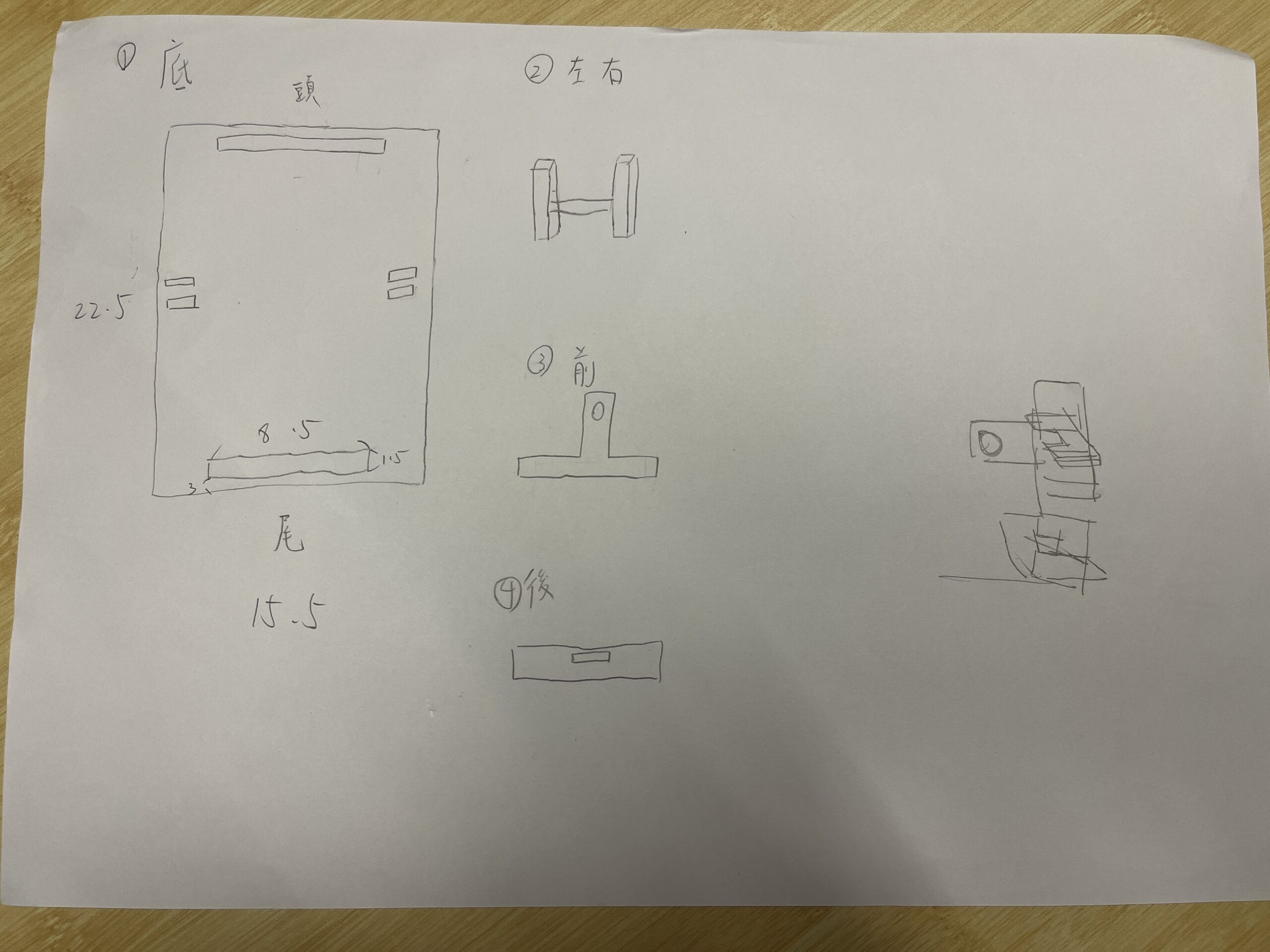
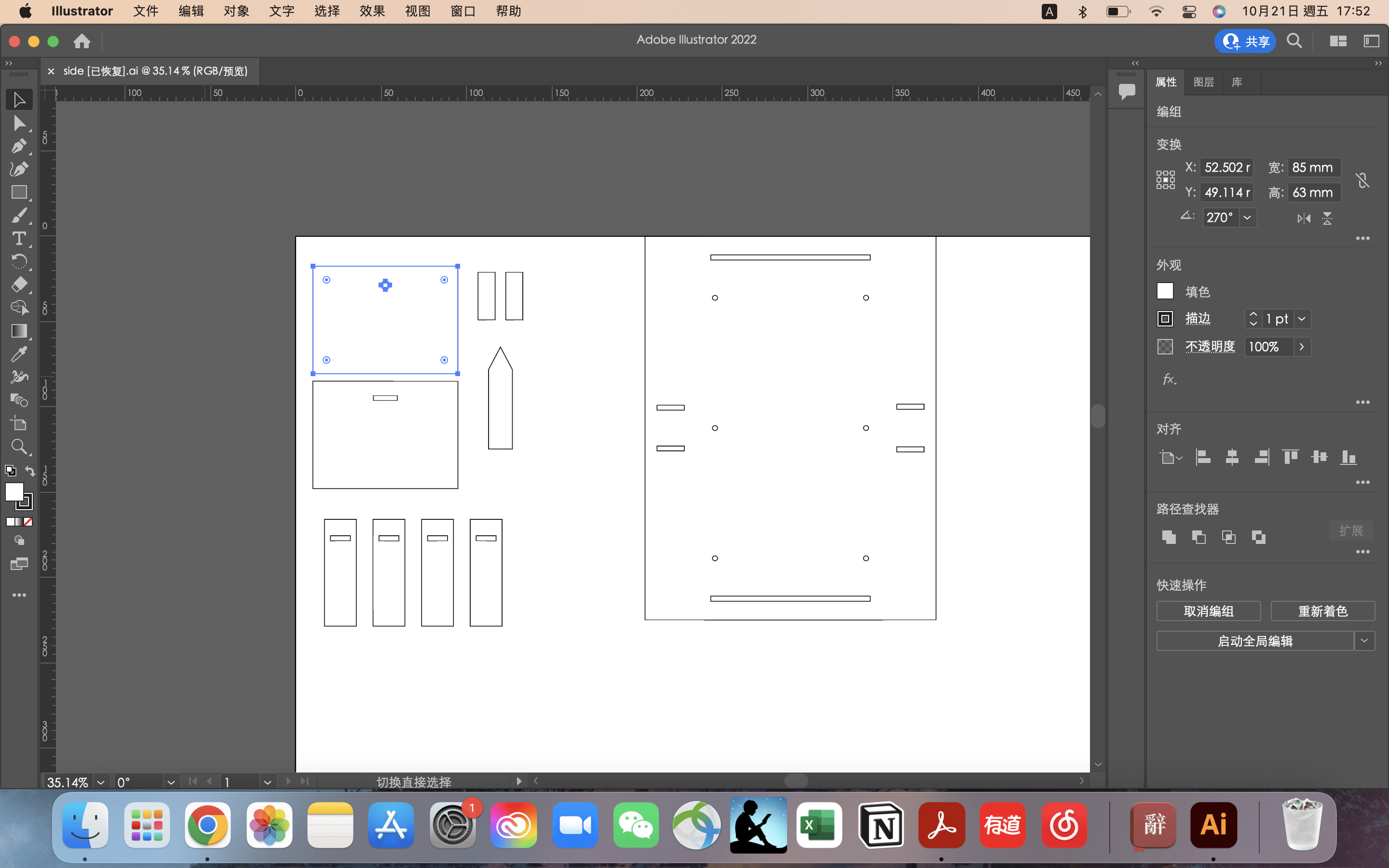
We first printed the bottom board to put on the car and test for the exact position of the servo, weapons, shields, and range sensors. Then, I tried to put the bottom board on the laser cutting machine to print additional holes I added, but there were some errors on the board that I needed to give up. I do not know if it is the location problem, but I indeed put the board in the up-left corner based on the instructions. I printed the file again using another wooden board.
The second version still got some problems. After doing the cardboard decoration to fix the range sensor and the IR sensor, we started to install the servo motors to test the code. However, we found the stack for holding servos is not that appropriate. In order to make the assignment work well, we decided to alter the location of the holes on the bottom board and print again.
While testing the third version, we discovered one serious issue. The holes on the wooden board do not match to hole on the car, so we can not use screws to fix the fabrication thing and the robot car. I guess it is because my computer kept shutting down that night, this may cause errors in the file that I did not notice. Thanks to Johnny’s assistance, we adopted his data for the holes and altered the file.
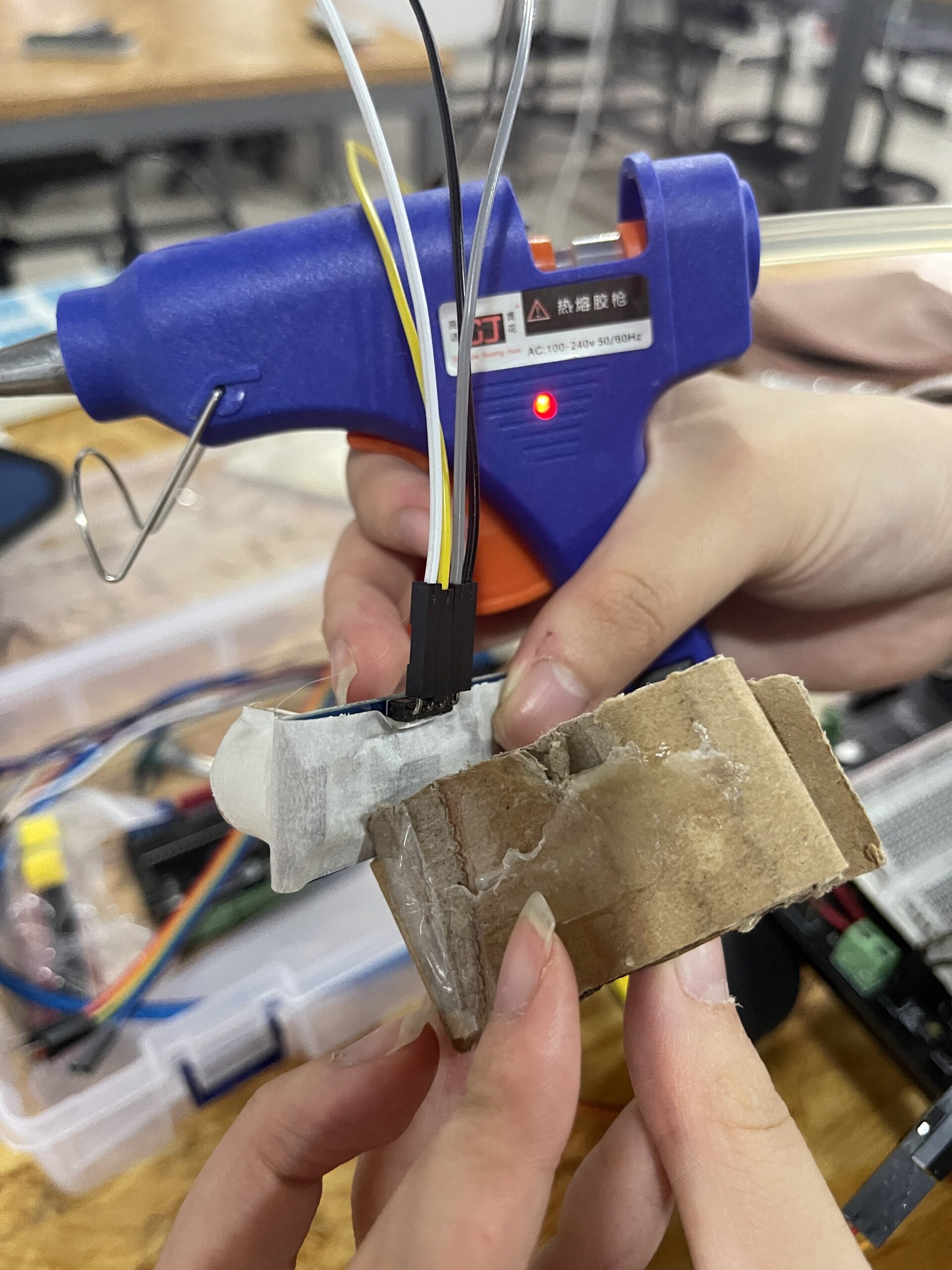
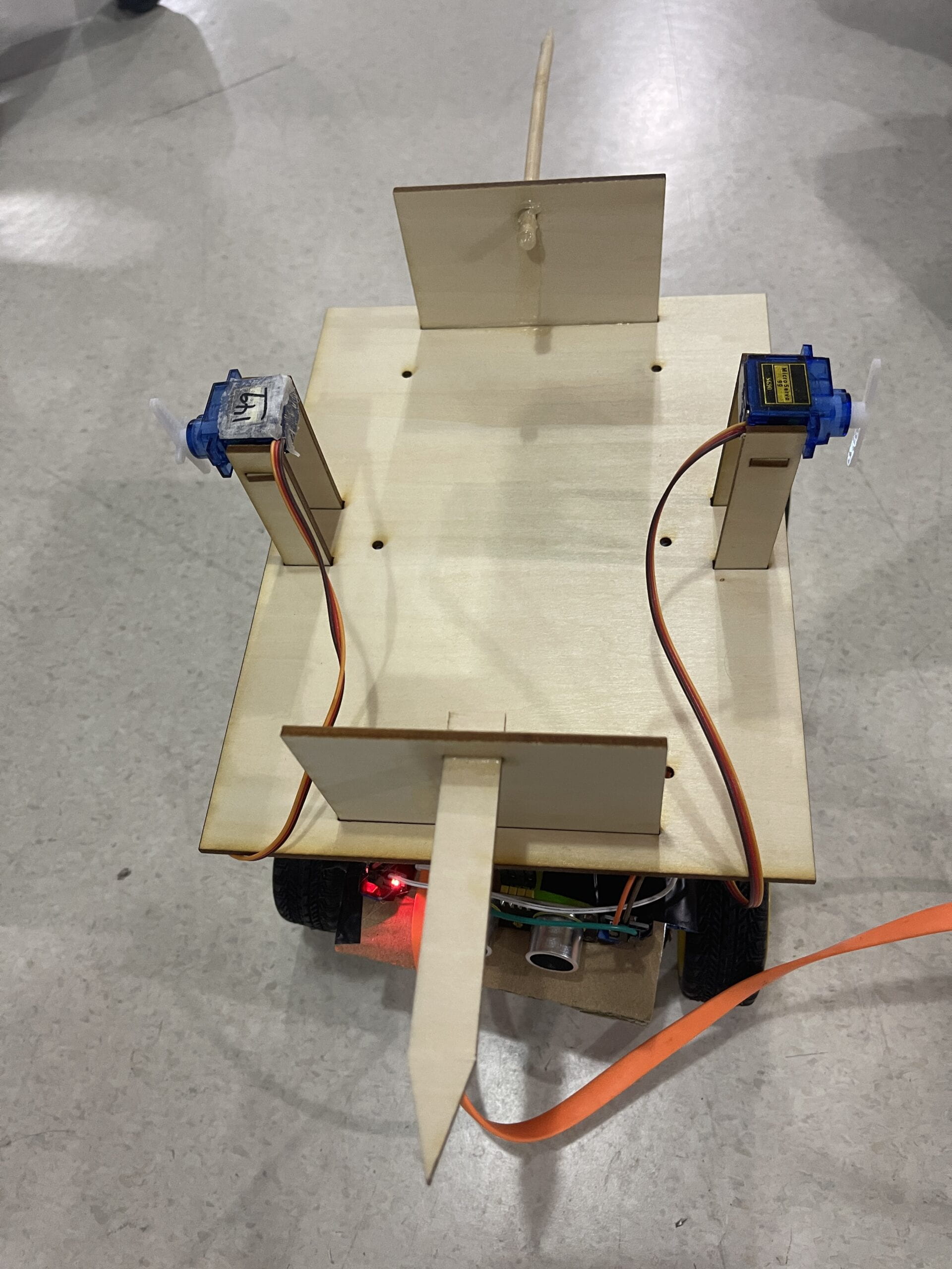
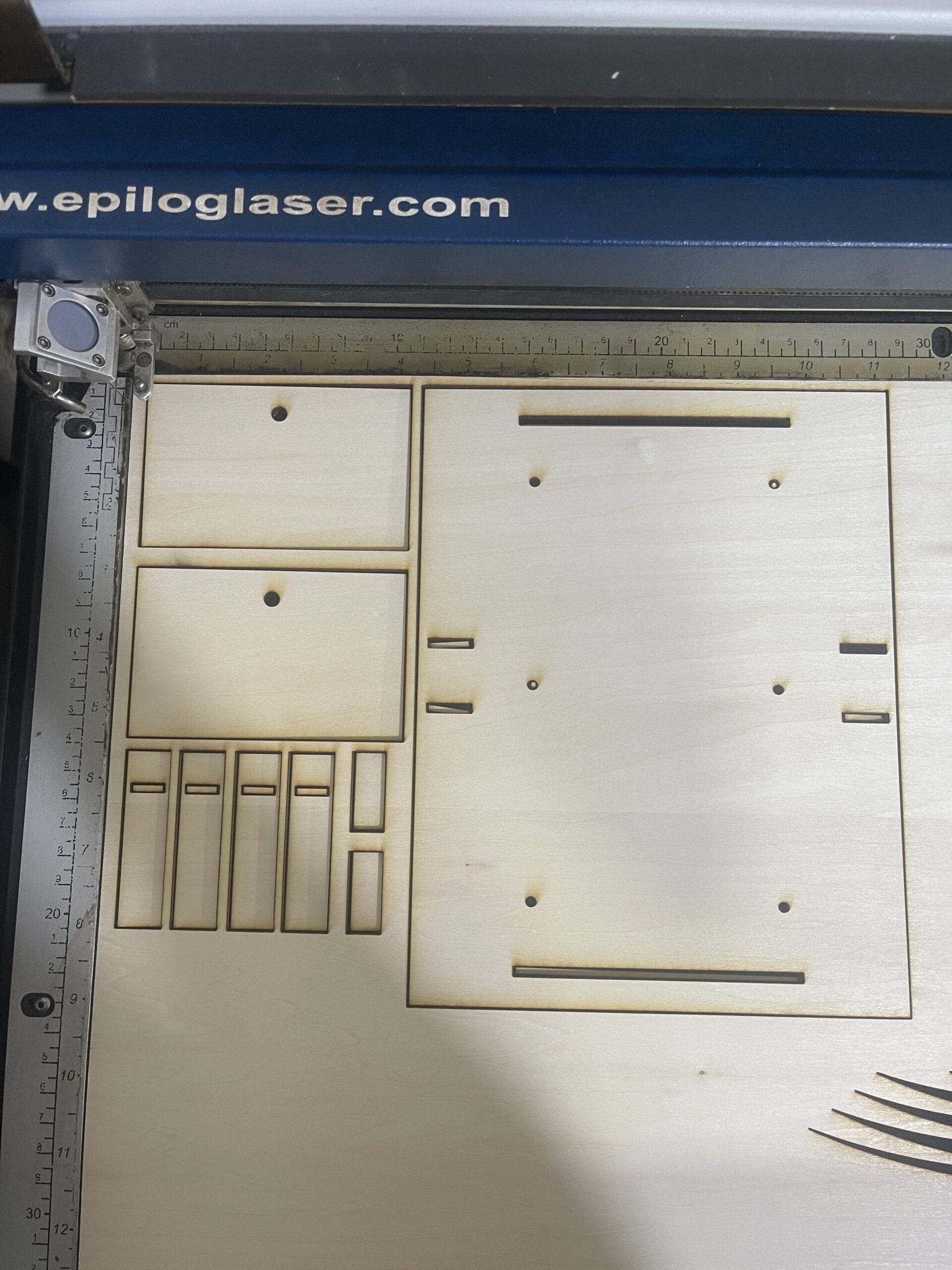
The fourth version loos perfect, we spent a lot of time using the 502 glue to combine the components. However, there were still some tiny errors making the side boards and bottom boards difficult to glue. I guess maybe because I chose another material by mistake and forgot to change the setting of the printer. As a result, we checked everything again carefully and printed the fifth time. Finally, we got the result we want.
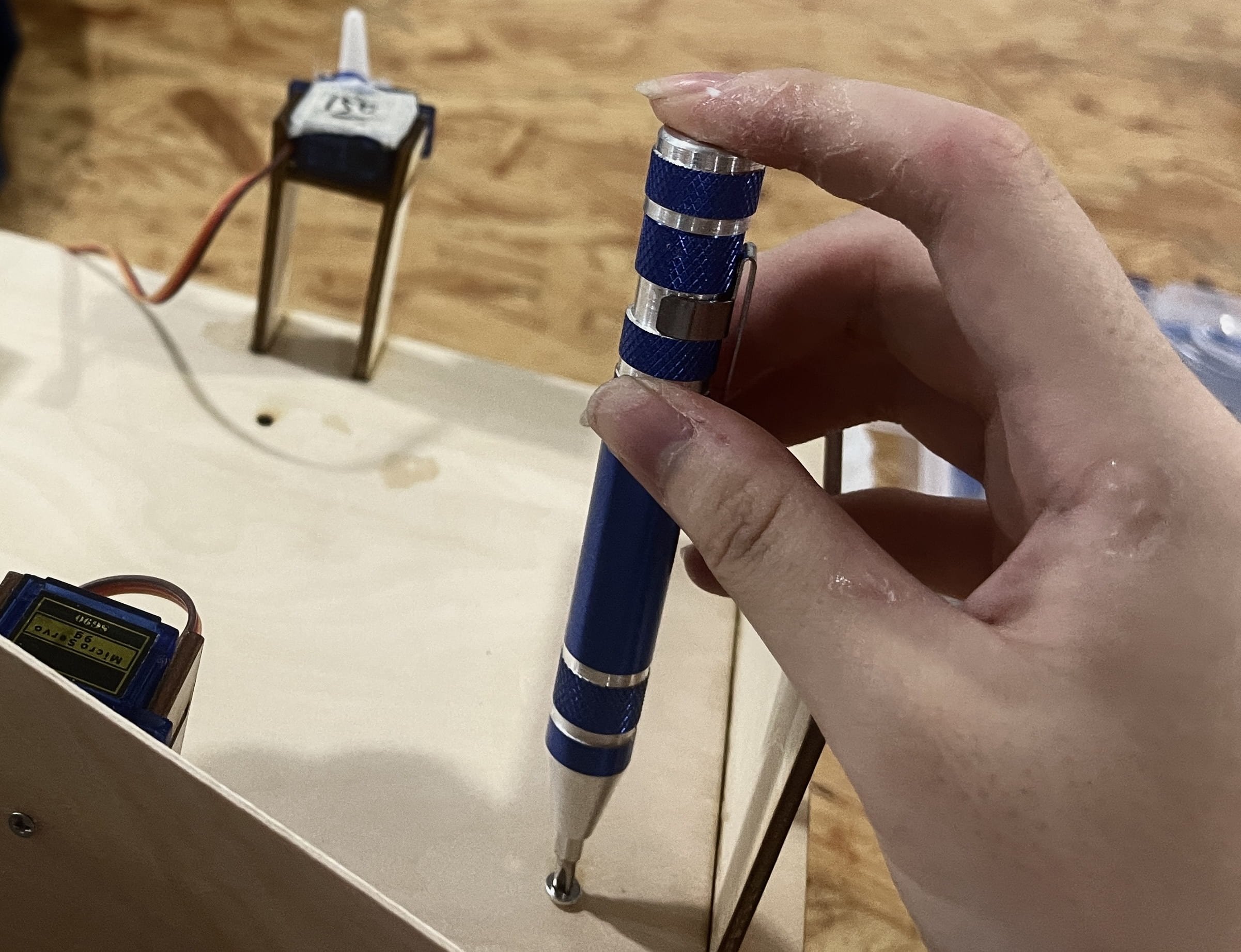
We tested the codes again and did some simple codes change. The shields can pop up when someone/ something approached the side of the car.
In the present day, I used a lot of tapes to fix the sensors and servo motors, and tested the code again.
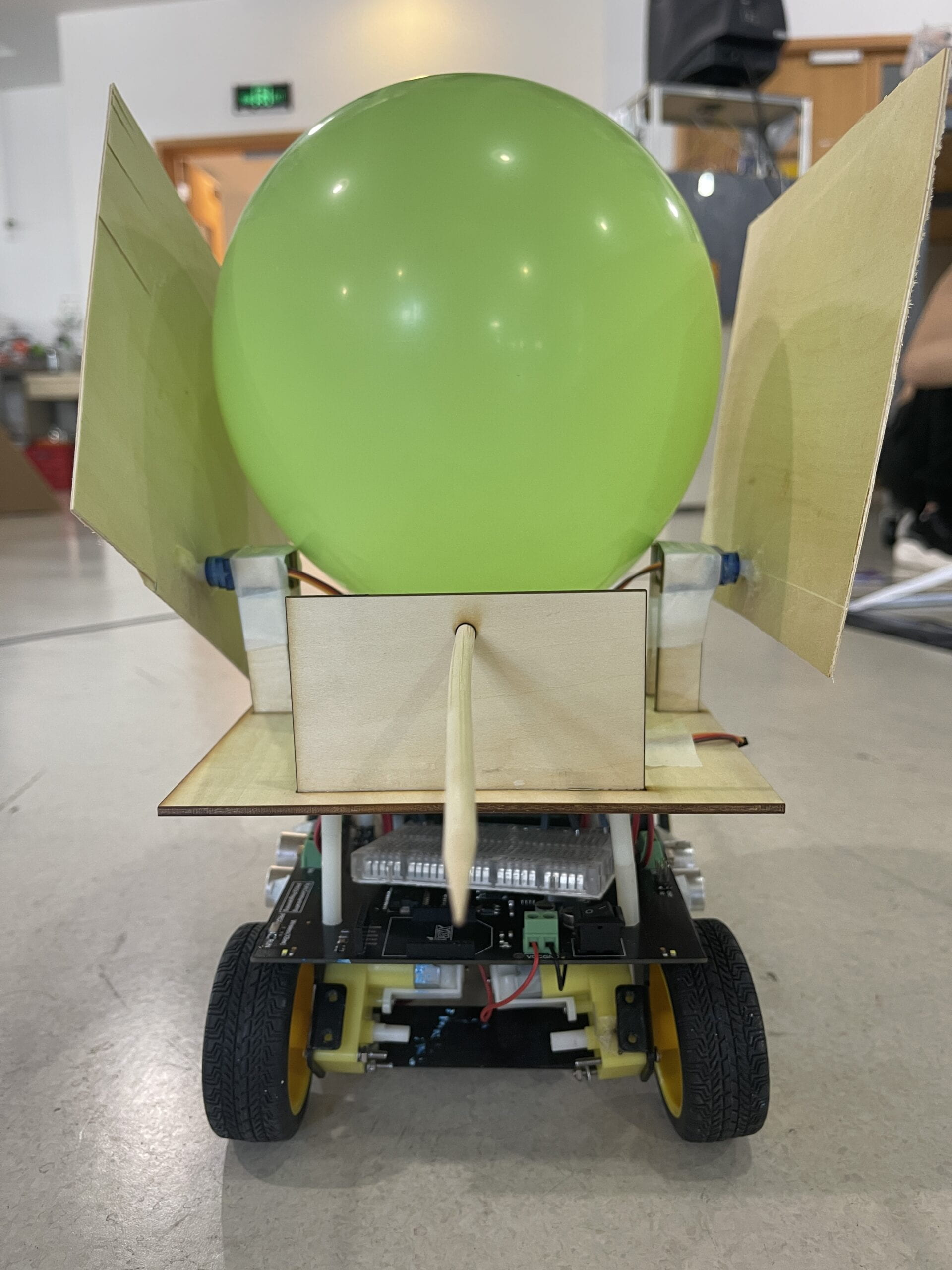
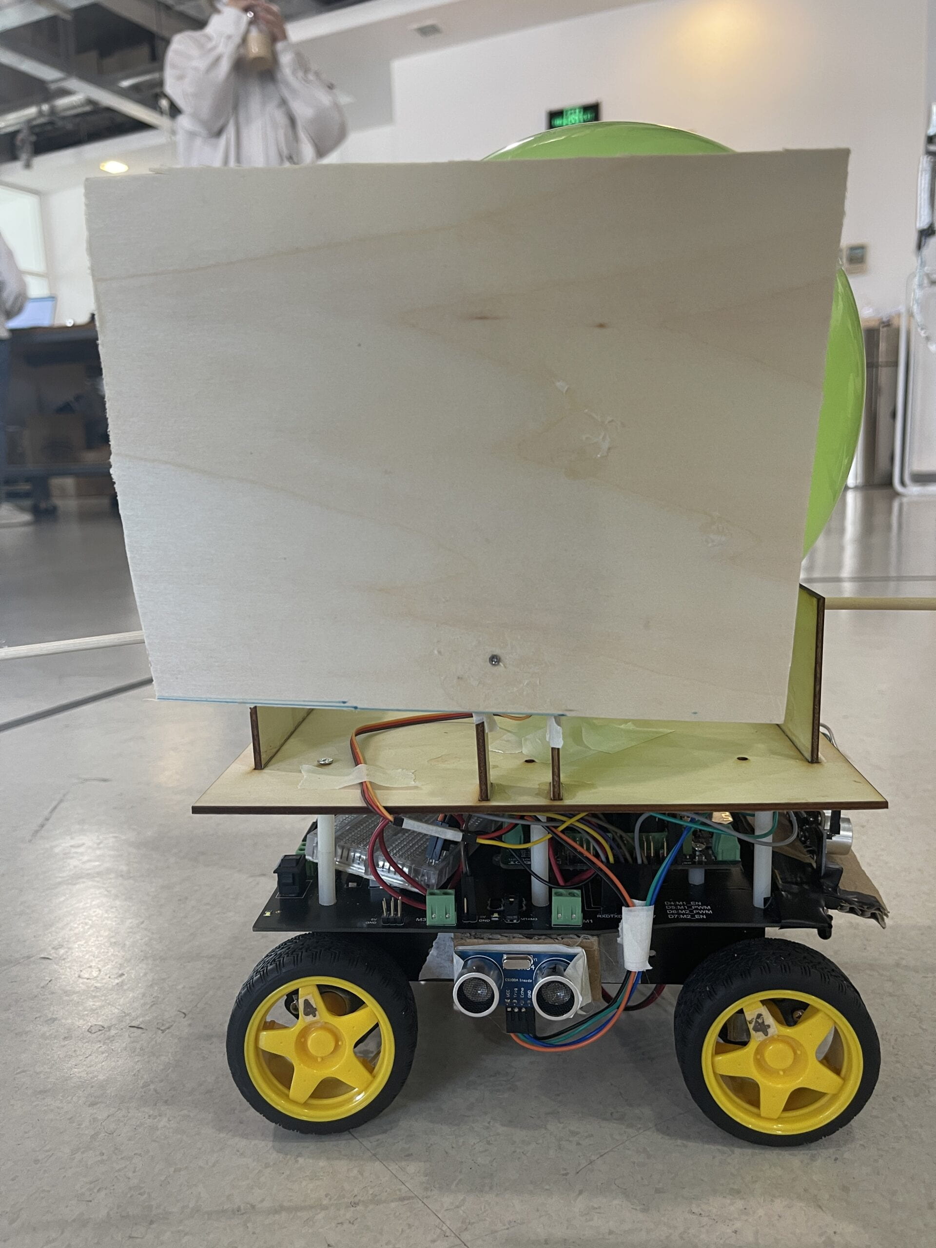
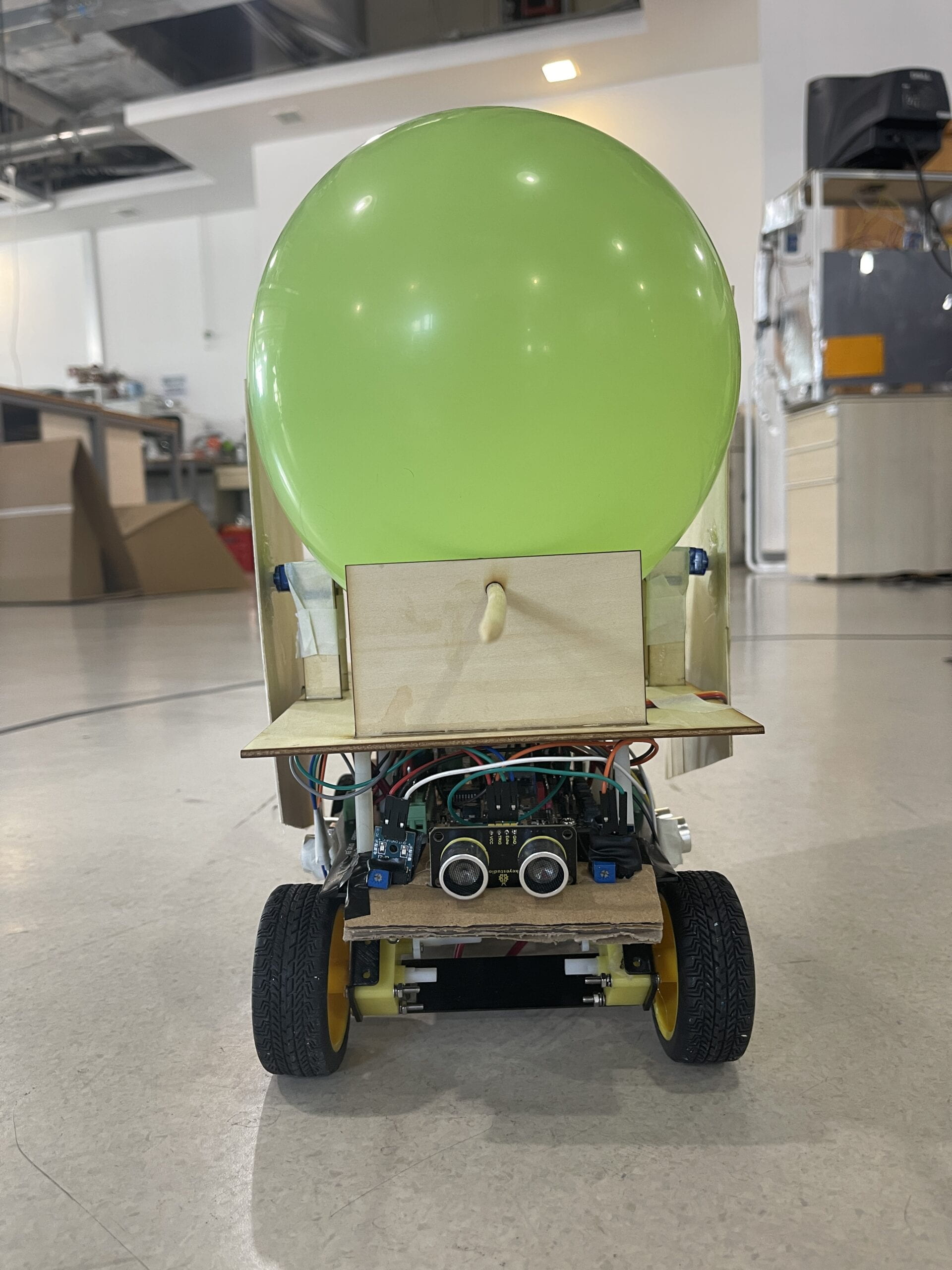
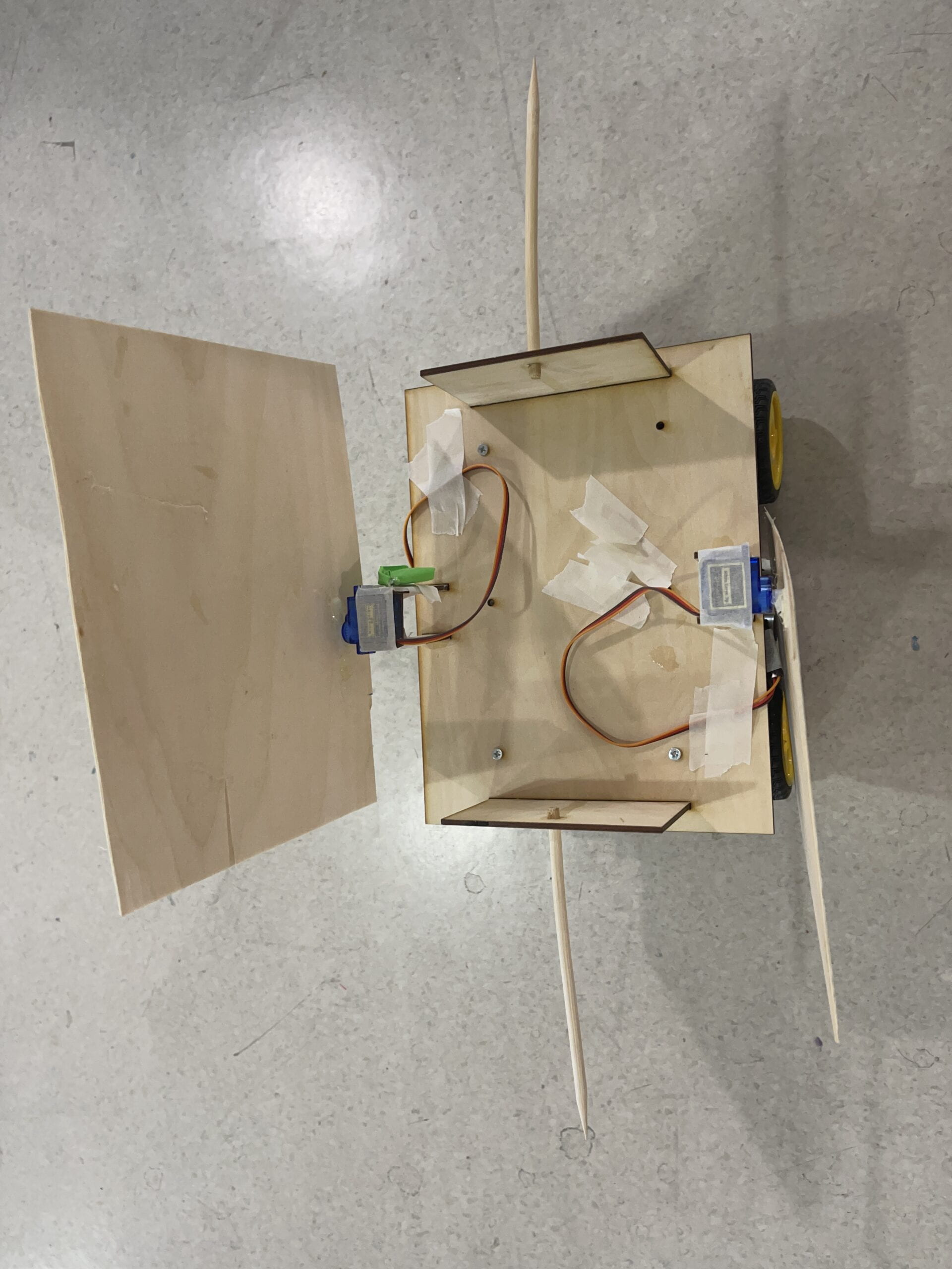
The video showed the first round of our robot. It works quite well, only one range sensor nearly fall off. Because the other robots were out of battery and keep leaving the black circle, our robot won.
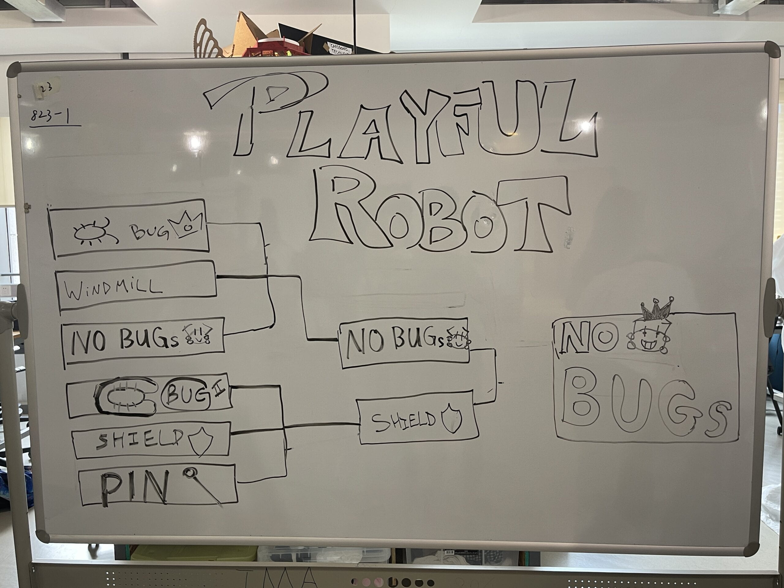
For the second round, because our weapons can not even attack the opponent’s balloon, our robot can only wait for death. “Boom!” We lost the game. Nevertheless, I think today’s competition is really interesting. Everyone’s robots have its own style and different functions. I felt the effort is super worthy.
Look! “Shield” (our cute robot) got second place!!!
Codes for Part Two
#define left A0
#define right A1
#include <Servo.h>
#define echoPinFront 3
#define trigPinFront 2
#define echoPinLeft 11
#define trigPinLeft 10

#define echoPinRight 13
#define trigPinRight 12

int pos = 60;
int sweepFlag = 1;

int speedPin_M1 = 5;     //M1 Speed Control
int speedPin_M2 = 6;     //M2 Speed Control
int directionPin_M1 = 4;     //M1 Direction Control
int directionPin_M2 = 7;     //M1 Direction Control


int URPWM = 3; // PWM Output 0-25000US,Every 50US represent 1cmk
int URTRIG = 10; // PWM trigger pin
uint8_t EnPwmCmd[4] = {0x44, 0x02, 0xbb, 0x01}; // distance measure command

int state;
#define GO 1
#define LEFT 2
#define RIGHT 3
#define TURN 4
#define BACK 5

int distLeft, distRight, distFront;
int IRLeft, IRRight;
int duration;
unsigned long startLeft;
unsigned long startRight;
boolean debounce;
boolean debounce2;

Servo myservo;
Servo myservo2;

void setup() {
  //declaring pin types
  pinMode(4, OUTPUT);
  pinMode(5, OUTPUT);
  pinMode(6, OUTPUT);
  pinMode(7, OUTPUT);
  myservo.attach(9);
  myservo2.attach(8);
  SensorSetup();
  Serial.begin(9600);
  pinMode(echoPinFront, INPUT);
  pinMode(trigPinFront, OUTPUT);
  pinMode(echoPinLeft, INPUT);
  pinMode(trigPinLeft, OUTPUT);
  pinMode(echoPinRight, INPUT);
  pinMode(trigPinRight, OUTPUT);

}

void loop() {
  shieldLeft();
  shieldRight();
  readSensor();
  rangeDetectionFront();
  rangeDetectionLeft();
  rangeDetectionRight();
  evalSensor();
  Serial.println(state);

  switch (state) {
    case GO:
      carAdvance(200, 200);
      //      delay(200);
      break;
    case LEFT:
      carTurnLeft(190, 200);
      delay(2000);
      break;
    case RIGHT:
      carTurnRight(200, 190);
      delay(2000);
      break;
    case TURN:
      carTurnLeft(190, 200);
      break;
    case BACK:
      carBack(200, 200);
      delay(1500);
      break;
  }


}

void shieldLeft() {
  if (distLeft < 30 && distLeft > 0) {
    //  servo
    Serial.println("spin");
    myservo.write(90);
    startLeft = millis();
    debounce = true;
  } else {
    if (millis() - startRight > 1000) {
      Serial.println("return");
      myservo.write(0);
    }
  }
}
void shieldRight() {
  if (distRight < 30 && distRight > 0) {
    //  servo
    Serial.println("spinRight");
    myservo2.write(90);
    startRight = millis();
    debounce2 = true;
  } else {
    if (millis() - startRight > 800) {
      Serial.println("returnRight");
      myservo2.write(180);
    }
  }
}


void SensorSetup() {
  pinMode(URTRIG, OUTPUT);                    // A low pull on pin COMP/TRIG
  digitalWrite(URTRIG, HIGH);                 // Set to HIGH
  pinMode(URPWM, INPUT);                      // Sending Enable PWM mode command
}

void evalSensor() {
  //line detected by both
  if (IRLeft == 1 || IRRight == 1) {
    state = BACK;
  } else {
    if (distFront < 50 && distFront > 0) {
      //倒退距离大于dist侦测距离,否则原路返回
      state = GO;
    } else {
      if (distLeft < 40) {
        state = LEFT;
      } else {
        //    转左优先于转右
        if (distRight < 40) {
          state = RIGHT;
        } else {
          state = TURN;
        }
      }
    }
  }

}


void rangeDetectionFront() {
  digitalWrite(trigPinFront, LOW);
  delayMicroseconds(2);
  digitalWrite(trigPinFront, HIGH);
  delayMicroseconds(10);
  digitalWrite(trigPinFront, LOW);
  duration = pulseIn(echoPinFront, HIGH);
  distFront = duration * 0.034 / 2;
  Serial.print("DistanceFront: ");
  Serial.print(distFront);
  Serial.println(" cm");
}

void rangeDetectionLeft() {
  digitalWrite(trigPinLeft, LOW);
  delayMicroseconds(2);
  digitalWrite(trigPinLeft, HIGH);
  delayMicroseconds(10);
  digitalWrite(trigPinLeft, LOW);
  duration = pulseIn(echoPinLeft, HIGH);
  distLeft = duration * 0.034 / 2;
  Serial.print("DistanceLeft: ");
  Serial.print(distLeft);
  Serial.println(" cm");
}

void rangeDetectionRight() {
  digitalWrite(trigPinRight, LOW);
  delayMicroseconds(2);
  digitalWrite(trigPinRight, HIGH);
  delayMicroseconds(10);
  digitalWrite(trigPinRight, LOW);
  duration = pulseIn(echoPinRight, HIGH);
  distRight = duration * 0.034 / 2;
  Serial.print("DistanceRight: ");
  Serial.print(distRight);
  Serial.println(" cm");
}

void readSensor() {
  IRLeft = digitalRead(left);
  IRRight = digitalRead(right);
}
void carStop() {                //  Motor Stop
  digitalWrite(speedPin_M2, 0);
  digitalWrite(directionPin_M2, LOW);
  digitalWrite(speedPin_M1, 0);
  digitalWrite(directionPin_M1, LOW);
}

void carAdvance(int leftSpeed, int rightSpeed) {       //Move FORkward
  analogWrite (speedPin_M2, leftSpeed);             //PWM Speed Control
  digitalWrite(directionPin_M2, HIGH);
  analogWrite (speedPin_M1, rightSpeed);
  digitalWrite(directionPin_M1, HIGH);
}

void carBack(int leftSpeed, int rightSpeed) {     //Move BACKrward

  analogWrite (speedPin_M2, leftSpeed);
  digitalWrite(directionPin_M2, LOW);
  analogWrite (speedPin_M1, rightSpeed);
  digitalWrite(directionPin_M1, LOW);
}

void carTurnLeft(int leftSpeed, int rightSpeed) {    //Turn Left
  //Serial.println("left");
  analogWrite (speedPin_M2, leftSpeed);
  digitalWrite(directionPin_M2, LOW); //right
  analogWrite (speedPin_M1, rightSpeed);
  digitalWrite(directionPin_M1, HIGH);
}
void carTurnRight(int leftSpeed, int rightSpeed) {    //Turn Right
  //Serial.println("right");
  analogWrite (speedPin_M2, leftSpeed);
  digitalWrite(directionPin_M2, HIGH);
  analogWrite (speedPin_M1, rightSpeed);
  digitalWrite(directionPin_M1, LOW);
}
Leave a Reply