Phototransistor

What does the sensor do?
phototransistors detect ambient light. Inside the cylinder is a little chip that generates current from long lead to the short lead when a light passes by. It also uses “less toxic ingredients” to produce than regular photo sensors, making transistors more envrionmental friendly (adafruit). Similar to a photoresister, both products produce “less current flow when darkened than when lighted” (Sensor Workshop at ITP).
How does the sensor work?
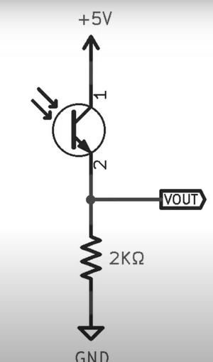
As a light-sensitive transistor, the more light passing the chip inside means the more current that will be induced. To use, connect the longer leg to power bus, and connect the shorter bus to ground via 1k-10k resistor. As an analog sensor, make sure that the shorter leg is also connected to an Analog input friendly pin on the Arduino. “When it’s dark, there’s almost no current flowing through the sensor or resistor and the analog voltage is near ground. When there’s light near the sensor, the current through the resistor will increase, raising the voltage” (adafruit). The voltage range can be adjusted through changing the resistor.
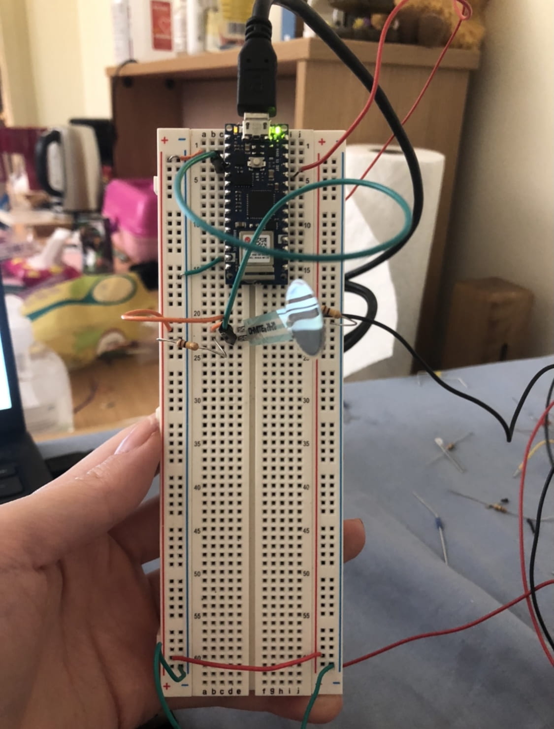
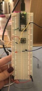
trying out the sensor
(input (A6) was the phototransistor; input1 (A7) was FSR that I was also playing around with — the left values on the serial monitor is the readings from the phototransistor)
I enjoyed using the sensor because it was pretty similar a photoresistor, which I was pretty familiar with. However, I did notice that phototransistors did not react sensitively to regular room light (whereas photoresistors do react to regular room light). Rather, it sensed flash light from my phone much better, and the input value increased depending on how strong the light was affecting the transistor. I thought it was interesting to see that the transistor almost seem to detect the distance of the light source (the input value increased as my phone’s flash light got closer to the transistor).
To clearly see the difference between a phototransistor versus a photoresistor, I tried both sensors in the same environment. Below is the result:
https://drive.google.com/file/d/1gIx-_bNpu0EwA2H6ZHHyVdx5KaMd5_rb/view?usp=sharing
In the video, the first number on the serial monitor is the phototransistor. Then, the second number is the photoresistor, while the third number is a FSR value that can be disregarded. As shown in the video, while the photoresistor is more sensitive room light, when the source of light changes to a lamp, phototransistor can be intepreted to be more ‘accurate’ in terms of how powerful the light is (depending on the distance from the light source).
What worked and what didn’t work? Any questions?
I’m still having a hard time figuring out what kind of specific situation (that is also practical in real life) would require a phototransistor than a photoresistor.
Circut/Example Code

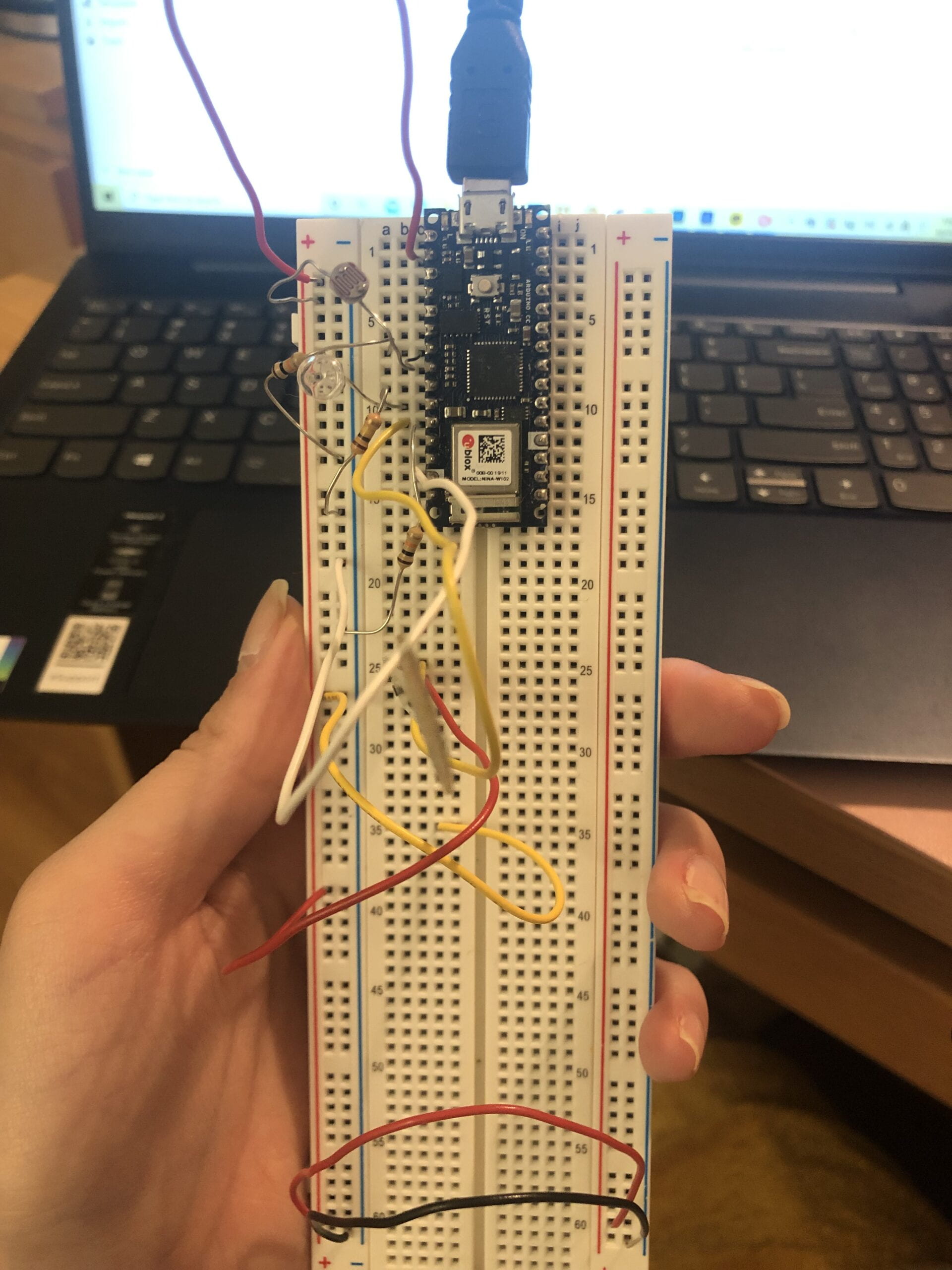
Phototransistor:
- connected to A6 (shorter leg) + 10k resistor from A6 to ground bus
- longer leg to power bus
Photoresistor:
- connected to A3 (shorter leg) + 10k resistor from A3 to gorund bus
- longer leg to power bus
potential applications of the sensor
Photoransistors may be better suited for scenarios that might require a specific light to be detected . On the other hand, photoresistors may be better suited for sensing the overall brightness of a spacial area.
Because the phototransistor seems to be more accurate in the sense that it can detect the distance of the light source, I thought the sensor might be applicable to helping humans maintain a safe distance from a light source. For example, the sensor could be implemented to glasses that lets the wearer know when the user has a monitor (laptop, tv, phone, etc.) too close to his/her face.
Another possible application of transistors might be found in parking spaces. Because cars have their headlights on when parking, phototransistors may be implemented on walls to prevent the car from backing up too far (by detecting the light intensity from the headlights which would technically be measured as ‘distance’). However, I realize that distance sensor would be much more reasonable.
Possible Project ideas
light tag game with a spin?
- everyone is in a dark room
- everyone is wearing a LED suit, but only the designated tagger (starts with a single tagger) has the LED suit turned on (like the picture below).

- participants will have the phototransistor attached to their shoulders
- timer will be set to 5 minutes
- tagger will run around and tag people on their soulders
- phototransistor will detect the light when tagged — this will trigger the LED suit to turn on
- Game ends when everyone has their LED suit on (tagger wins) OR when the timer goes off before all LED suits are on (remaining people win)
Building a (small and unreasonable) Project
alarm clock?
Using p5, phototransistor, and FSR, I created an alarm clock.
How it works:
- when the environment is dark, ‘resting’ mode is the default; there is no alarm
- resting mode = dark background, yellow moon, no alarm, “resting…” text
- when the phototransistor senses light (anything above 100), ‘morning’ mode turns on – I made this value small because phototransistors are not too sensitive when detecting room ambient light, and I thought the same thing would apply for regular sunlight coming into the room when it’s morning
- morning mode = bright background, orange sun, alarm sound goes off
- the user has to to press the FSR (over 400 value — it’s not that hard) in order to stop the alarm sound
- the entire loop will stop (including the movement of the sun), and ‘good morning!’ message will pop up
- when playing videos, make sure that the sound is on!
computer view:
https://drive.google.com/file/d/1XRFL2nGojXwABttPIq70-C6KNfNDYAmS/view?usp=sharing
p5 sketch:
https://editor.p5js.org/jiwonyu/sketches/EF_z3_dEI
websites referenced:
https://itp.nyu.edu/archive/physcomp-spring2014/sensors/Reports/PhototransistorsPhotocells.html
https://cdn-shop.adafruit.com/product-files/2831/HW5P-1_2015__1_.pdf