Pcomp Final Documentation

Project title and description 

Title: Woman 

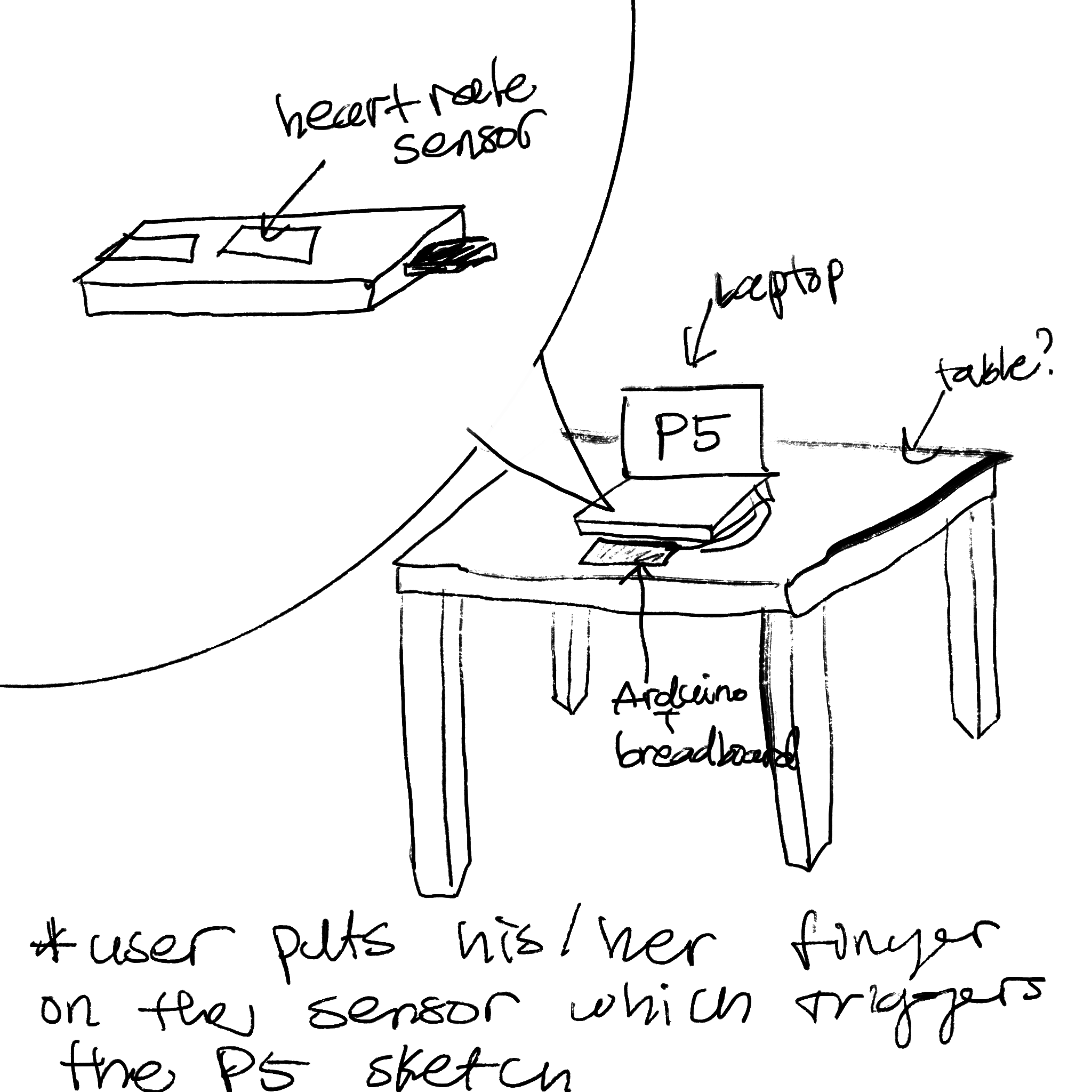
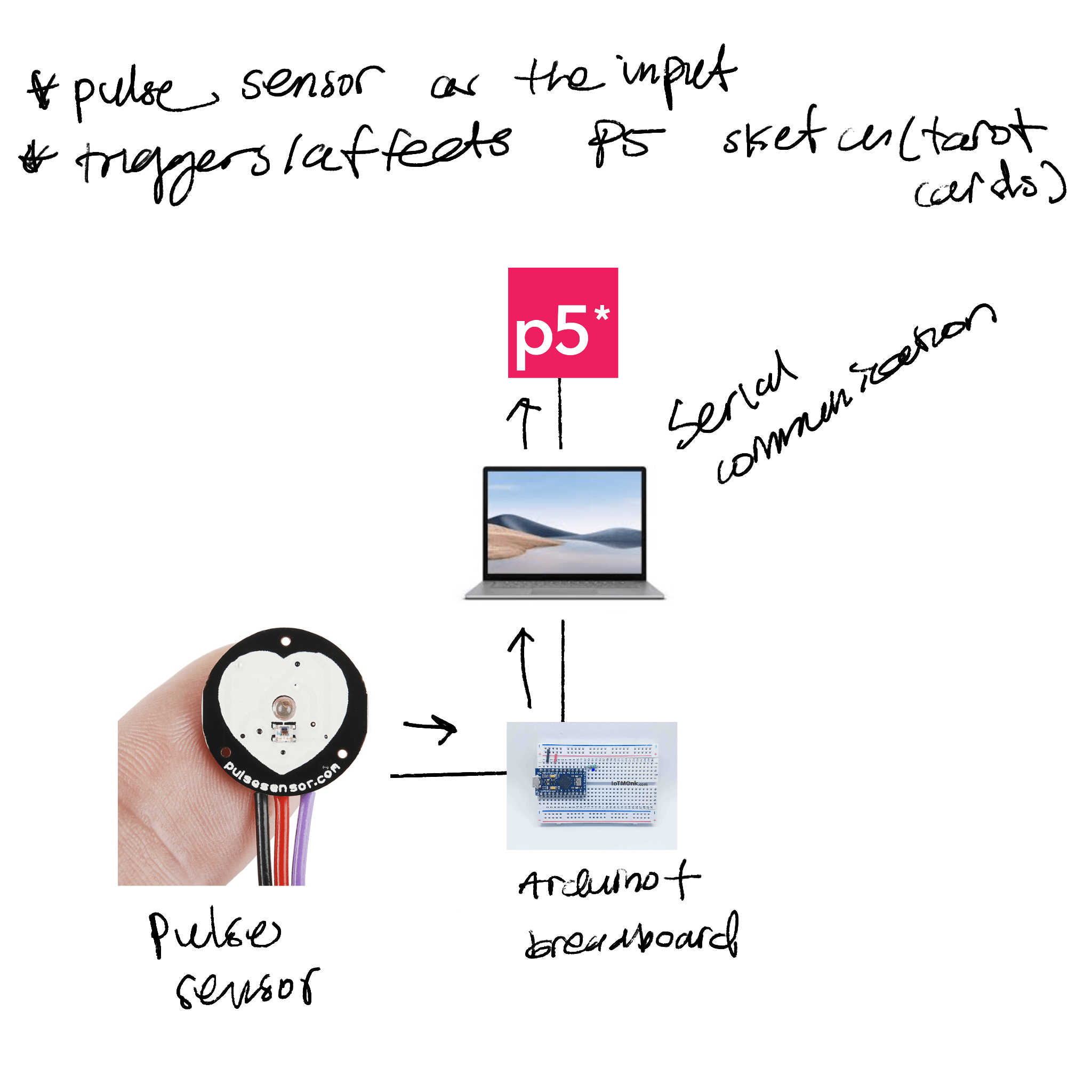
This project was a sociopolitical commentary on the unreasonable consequences that come with being a woman in New York. There is a heart rate sensor that controls the on/off of several buzzers. The design of the project had a guiding question in mind: “why would a woman with heels have a heart rate of 120bmp?”

Personally, the answer was pretty clear: she’s running away from something. With this in mind, I wanted to incorporate what is traditionally found ‘feminine’ by the society, heels and corset, and turn it into a statement. 

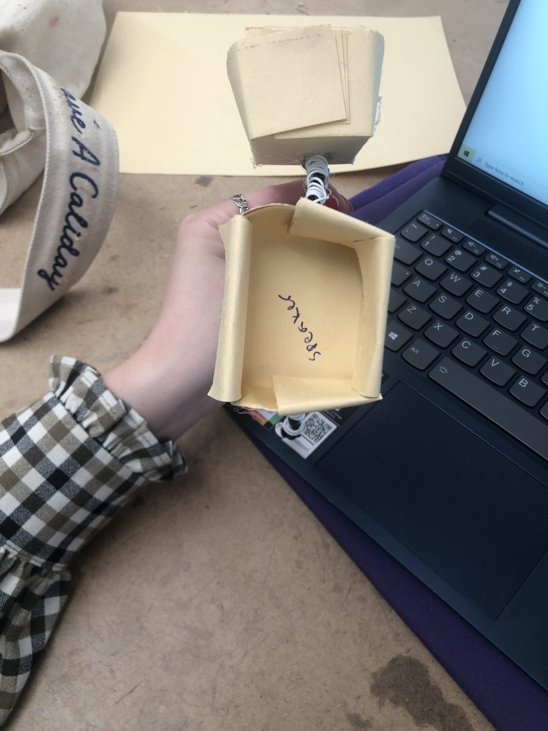
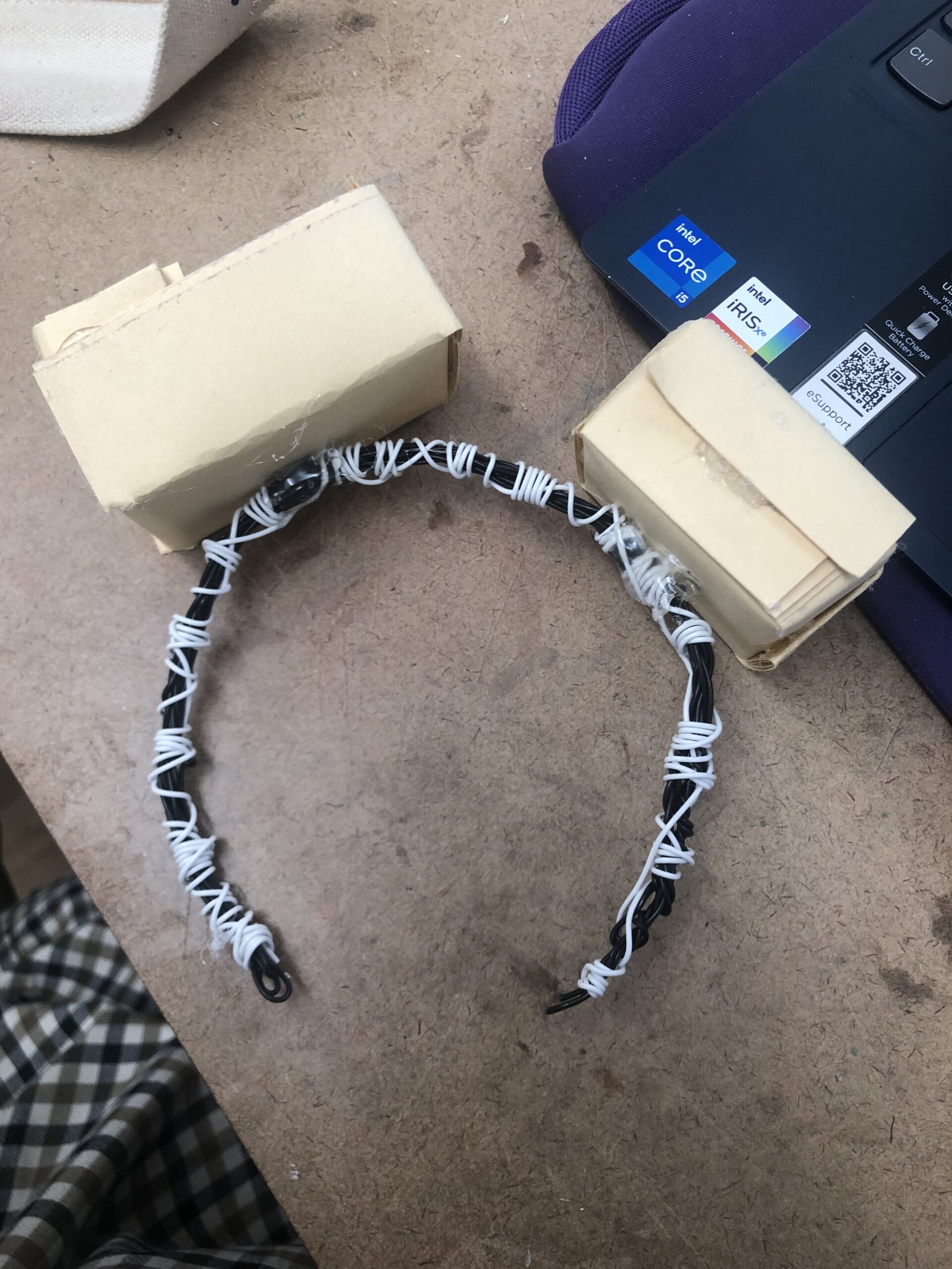
The skeletal and robotic aesthetic of the design was purposeful as well. The skeletal aesthetic was chosen to demonstrate the vulnerability a woman feels while being alone in New York City. Similarly, the robotic aesthetic accompanies this by demonstrating a woman’s desire to become ‘unhuman’ so that she is no longer looked upon as a viable prey by strangers. When will women be stopped being seen as a sexual object? Do women need to be non-human?

Both aesthetics work to showcase woman’s complex, fearful emotions that are derived from hypersexualization of women by men. 

Final video documentation 


Four buzzers working when heart rate is high: 

https://drive.google.com/file/d/1oLpFujUUGE0clwwpWNmhLGigYjW6OeOh/view?usp=sharing

https://drive.google.com/file/d/1bvPxUTi7mnXNqR4YST72-dr_osVwhMZm/view?usp=sharing

Front picture: 

https://drive.google.com/file/d/13VGQJTQJObcIePj2O3kSA0u-EqpigJNm/view?usp=sharing

circuit: 

https://drive.google.com/file/d/17obAi29YSiQq9TNCk8mewV65KGjI6nBr/view?usp=sharing


Circuit and Code documentation

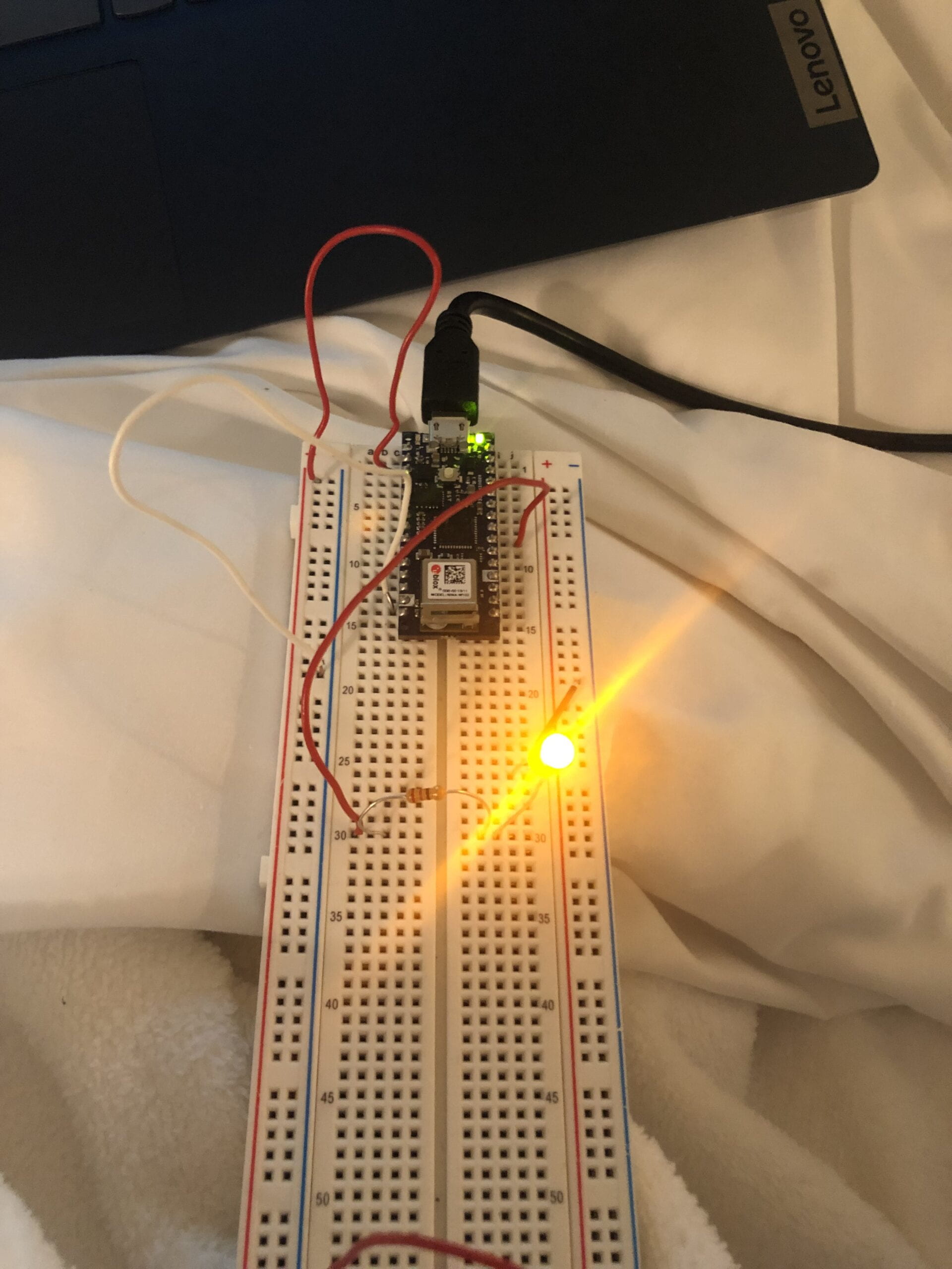
Below is my my circuit with just one buzzer. Because it was my first time using the buzzer, I wanted to do a simple test before adding more: 

https://drive.google.com/file/d/17ayJOQ-VKonmJ_zZwHbe7hRSQPPWzSQ7/view?usp=sharing

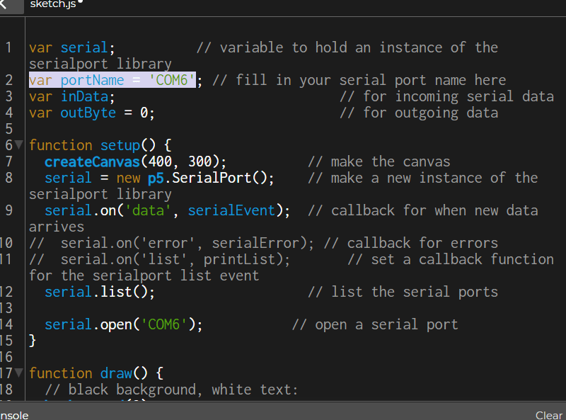
Below is the final code that utilizes four buzzers: 

//#include <Tone.h>

//PLUSE SENSOR
#include <Wire.h>
#include "MAX30105.h" //MAX3010x library
#include "heartRate.h" //Heart rate calculating algorithm

MAX30105 particleSensor;

const byte RATE_SIZE = 4; //Increase this for more averaging. 4 is good.
byte rates[RATE_SIZE]; //Array of heart rates
byte rateSpot = 0;
long lastBeat = 0; //Time at which the last beat occurred
float beatsPerMinute;
int beatAvg;

void setup() {
// put your setup code here, to run once:
particleSensor.begin(Wire, I2C_SPEED_FAST); //Use default I2C port, 400kHz speed
particleSensor.setup(); //Configure sensor with default settings
particleSensor.setPulseAmplitudeRed(0x0A); //Turn Red LED to low to indicate sensor is running
int output = 2;
int output1 = 4;
int output2 = 5;
int output3 = 6;
pinMode (output, OUTPUT);
pinMode (output1,OUTPUT);
pinMode (output2, OUTPUT);
pinMode (output3, OUTPUT);
}

void loop() {

// put your main code here, to run repeatedly:
long irValue = particleSensor.getIR(); //Reading the IR value it will permit us to know if there's a finger on the senso0.r or not

if (irValue > 7000) { //If a finger is detected

if (checkForBeat(irValue) == true) //If a heart beat is detected
{
Serial.write((byte) 1);
//We sensed a beat!
long delta = millis() - lastBeat; //Measure duration between two beats
lastBeat = millis();

beatsPerMinute = 60 / (delta / 1000.0); //Calculating the BPM

if (beatsPerMinute < 255 && beatsPerMinute > 20) //To calculate the average we strore some values (4) then do some math to calculate the average
{
rates[rateSpot++] = (byte)beatsPerMinute; //Store this reading in the array
rateSpot %= RATE_SIZE; //Wrap variable

//Take average of readings
beatAvg = 0;
for (byte x = 0 ; x < RATE_SIZE ; x++)
beatAvg += rates[x];
beatAvg /= RATE_SIZE;
}
Serial.println ((byte) beatAvg);
}
if (beatAvg > 120)
{

digitalWrite (2, HIGH);
digitalWrite (4, HIGH);
digitalWrite (5, HIGH);
digitalWrite (6, HIGH);
delay (100);
digitalWrite (2, LOW);
digitalWrite (4, LOW);
digitalWrite (5, LOW);
digitalWrite (6, LOW);

}else {
digitalWrite (2, LOW);
digitalWrite (4, LOW);
digitalWrite (5, LOW);
digitalWrite (6, LOW);

}
}
}

Process documentation

Buzzer

Below is the video of the buzzer working: 

https://drive.google.com/file/d/170D97phMbM5RyZFKXa4xLUX0vk1eIibS/view?usp=sharing

Then, I wanted to see how I wanted the buzzer to sound. In the previous video, the buzzer noise is continous. On this video, the buzzer noise is seperated my a short pause, and it repeats. 

https://drive.google.com/file/d/1FapTNGGiC6kFAT1N1M-wCULv5zN0p2eW/view?usp=sharing

I also played around with tone () to change frequencies of different buzzers. I thought this would create more of a starking sound. Below is three buzzers going off at the same time with different tones. 

https://drive.google.com/file/d/1DnGWYlyaHk8TQjmevKWoLigLDTHNruBO/view?usp=sharing

I did not have the heart rate sensor when I was testing the buzzers out. However, I still wanted to test if I could have an analog input control the on/off of the buzzers. As a simple protoype, I used a photocell to mock this set up. In this video, the buzzers only go off when the ‘room’ is dark. 

https://drive.google.com/file/d/1lRb4hBtq5-ZhbBIxhH7QB5gTk5DIOnpQ/view?usp=sharing

Pulse Sensor

I had a hard time working out the pulse sensor. Because both of my pulse sensors did not work, I tried my code (it was an example code) on one of my peer’s, Max’s, pulse sensor (his was working). Below is a video of that: 

https://drive.google.com/file/d/1NfYk_a58UlTk7V2DRARuIBotlHj1mHrv/view?usp=sharing

Unfortunately, I could not borrow his sensor because he was using it for his project and the winter show. I bought three more sensors in hopes that one of them will work. 

After many many tries (I mean MANY 🙁 ) , the pulse sensor started to give me readings. Below is a demonstration of that: 

https://drive.google.com/file/d/1oQ_Nf-gvkQcXCqxysGJrZ6OoyOfqFYwX/view?usp=sharing

However, as soon as I tried to connect the buzzers to the circuit as well, my the Arduino stopped working, and the green LED is not turning on.


Challenges 

One of the saddest momments of doing this project was when I was trying to work the pulse sensors. Purchased from Amazon, I had high hopes for the pulse sensor, since it had the best ratings (and peers from my class recommended it). However, despite having two sensors, both of them ended up not working. 

I know that for the first sensor, I soldered wrongly, which was totally my fault. Learning from my mistake, I asked Faith (soldering queen) to solder my second sensor. It turned out great, but the sensor itself did not turn on at all. 

I had to order 3 more sensors from Amazon on that day. 

Update: turns out I ordered 5. 

After four of my sensors did not turn on, my friend volunteered his Arduino to me. Thankfully, his Arduino turned on my pulse sensor! All along,  I think I was having Arduino problems. 

Below is serial plotter sensing my pulses. 

https://drive.google.com/file/d/1umq-ZXXMWMB85y57w2KhmuV1QA2X5GI1/view?usp=sharing

However, for some reason, my computer stopped reading the port from the Arduino? I thought it was a cable problem, but when I used another cable to test it out, my computer still did not read my port (no green led was turned on). 

Below is a picture showing how the Arduino is not turning on even while it’s connected to my laptop: 

https://drive.google.com/file/d/14Vwftqn9sNiM2Lf7zs5m8Nud_7PPpy2H/view?usp=sharing

I would borrow another Arduino from the shop, but I am banned….

My Arduino started to heat up, and I wasn’t sure what the problem was. I ended up just rewiring everything, and the Arduino started to work fine again. 

In the Future

If I had more time to work on this project, I would incorporate physical computing to the decorative wearbles that function as an accesory/statement piece as of right now. I think it would be cool to have different sensors read different dangers from the streets. For example, having a distance sensor attached to the top piece to detect strangers from coming too close would add another layer to the project. 

I would also love to learn more about fashion/clothing fabrication in general and try to create an actual wearable clothing that would still contain the skeletal, robotic aesthetic. 

Future display 

Being a commentary piece, I cannot see this project being ‘used’ by other users. Rather, I envision this piece to be displayed/installed in appropriate places that have affiliations with raising awareness for sexaul assault. 

Ideally, I think having this piece in a museum-like setting would be great. I imagine there to be a button that a user can press to hear the buzzers go off (instead of the heart rate triggering the buzzer). Regardless, the pulse sensor would still be attached to the project, and how and why it triggers the buzzers would be explained in the description. I just think a button will be an easier interaction that would still showcase the effects and purpose of the piece. 


Final Planning

1) installation plan
2) system diagram
3) BOM (Bill of Materials)
4) Project Timeline

11/30 –

1. figure out how I want to utilize the pulse sensor 

2. figure out which pulse sensor would be the best

3. order pulse sensor 

12/3 –

  1. breadboard wiring
  2. code

12/6 – 

  1. finish code
  2. attempt to serial communicate

12/8 – 

  1. user testing

(12/13) – 

  1. keep trying if i cant get it by the 9th


Final prototype

My idea is a bit hard to build with a paper, so I utilized wires and papers. 

I wanted to create a headband with external speakers attached (kind of like ears). When the input is right, the two speakers (one on the left and one on the right) will play a harmonious chord: I was thinking maybe E and B. However, when the input is wrong, it will play unharmonious chord: I was thinking maybe Eb and E.

note: the chords may change as I make more progress. 

For the input, I was maybe thinking of using a heartbeat sensor and google teachable machine that would detect when someone is happy (the camera would detect smiling face vs regular face). 

The point of the project is to fill a space with sound depending on people’s moods. If one is happy, the headband will produce a beautiful sound, whereas if the user if unhappy (or nervous) the sound will be turbulent. 


The two boxes I made ended up being VERY uneven. That was not intended. 

Although I am pretty set on the output, I am still trying to figure out the input. Is a hearbeat sensor necessary? I want to make a headband that can demonstrate the user’s moods with sound, and I am still trying to explore the possible input options that would best execute what I want. 


Sustainable Material Research

Biomaterial from Soil -celluose sheet
1) what is the material?

According to the distributor, this “leather-like material from bio-cellulose” is grown from the “Streptomyces bacteria found in soil.” The material is 100% biocellulose. 

Streptomyces: bacterial explorers | Microbiology Society
2) what can it be used for?

The suggested applications by the distributor is the following: 

  • Accessories
  • Apparel
  • Automotive: Interior
  • Furniture
  • Home Appliances
  • Homewares
  • Interior Walls
  • Jewelry
  • Lighting (Lamp)
  • Packaging
  • Partitions
  • Tabletop
  • Work Surfaces

These leather like sheets have “uneven, but smooth surface, and is translucent to opaque naturally colored in different shades of brown.” Just like a regular leather, these sheets are flexible (rubbery) and durable. The sheets are also customizable and ccan be “reproduced at different thicknesses to suit different garment purposes.” In terms of measurements, “the material can be customized to size within 75 cm by 140 cm (30 in by 55 in). ”

3) where can you source the material? can you get a sample?

The sheets are made “through a reaction between the parent and added substances, which can be observed after 1–7 days.” “A thin, opaque white sheet starts to form on the surface. After 36–40 days, the cultured bacteria is fully developed into a cellulose sheet with a thickness of approximately 0.7 cm to 1 cm (0.28 in to 0.39 in).” The distributor’s company name is Indin Studio, and their headquarters are based in Thailand. Currently  no samples are available. 

4) are there projects made out of the material? would you like to use it in your project?

I could not find any projects made with the material on Google, but I think this material would have an interesting application to wearables and furnitures. I’d also love to play around with making the sheets to form human-like skins. I think the irregularity in texture would add a unique, maybe a little grotesque touch to human skulptures. I’d also like to play around with the durability of the material: how well does it perform under rain? could it possibly replace real leather? It is it sewable? How hard is it to cut? 

The description says that the material is rubbery, which makes me feel like the sheets would be hard to manipulate. I’m curious to see if it’ll be similar texture to pig skin? 

5) include images/videos of the material

https://www.materialconnexion.online/database/customer/account/login


Keyboard Lab

Breadboard View: 


After I uploaded the Arduino code, the serial monitor looked like the following: 

To be honest, I am not sure if that’s what it’s supposed to look like, but since I was seeing words on the monitor, I moved on. 

Then, I attached the LED and put commands so that the buttons could control the keyboard. The following is a video demonstrating the result: 

https://drive.google.com/file/d/1zPNUwNswW-tV5iCM64bUjiscBg-rTQwR/view?usp=sharing

The LED lit up when I pressed the first button.  However, the rest of the four buttons did not give me any input when I opened up my notes app to type something. 

On another note, my caps lock was on when the LED was lit — I am not sure why. Also, my mouse started to function oddly — I couldn’t really click left, and I also could not copy and paste using ctrl + c/v. 

I also had a lot of port problem, and the Arduino kept saying that I did not have a valid JTAG interface. However, after resetting my Arduino and unplug/replugging the USB cord, the connection issue was solved. 

I will continue to work on it and put any updates. 


Project 2 Research

I found a project that uses Arduino Uno and a buzzer to indicate a change in bitcoin price. 

https://www.instructables.com/Bitcoin-Price-Indicator-Using-Arduino/

I liked how it keeps record of the change in price every second — it is a real-time gadget that could actually be pratical in real life (at least to those who really love bitcoin). 

I also liked how u r g e n t the buzzer sounds when there is a change in price — I also appreciated the simplicity of the circuit. 

The interaction works like this: 

  1. Using this code,  https://github.com/Prabeen-Raj/Bitcoin-Price-Indicator/blob/main/BTC%20price%20indicator.py , python scraps the price of bitcoin in real time, every second. 
  2. “It will add the value of Bitcoin in list stored in variable price” ( ). 
  3. Then, it will compare the current value with previous value.
  4.  

    “If it is not same, it will send word H it makes the Pin State High” ( ).

  5. After 2 seconds, it will send data L in the serial communication which makes the pin state Low” ( ).

–– If you make a similar project, what would you do differently?

If I was making a similar project, I would have two-three outputs. For example, I would have three different colored LEDS (red, yellow, green/blue?). Yellow LED would be the ‘default’: it will light up when the price of the bitcoin is the same as the previous value. 

Then, red LED would turn on (and yellow LED would turn off) if the current value is less than the previous value. Similarly, the green/blue LED will light up when the value of bitcoin is higher than the previous value. 

It’d also be interesting to control the brightness of the LED based on the value. For example, if the value of one bitcoin is greater than 60,000, the brightness would be really high on the green/blue LED. 

I think this would be a better, more comprehensive use of bitcoin value tracker. The user would be able to see in a glance the pattern of bitcoin values fluctuating. 

Serial Input/Output to P5

Serial Input

Serial input lab went smooth sailing — I was able to follow every step with appropriate results coming back to me. I enjoyed being able to control what is on the screen with a physical sensor, and it reminded me of the alarm clock that I made for sensor research. Below are the videos from the lab instructions I followed: 

The only ‘problem’ I had with the input lab was the instability of the potentiometer. The one that I had did not stay still on my breadboard, so I had to angle it in an odd way and hold it down while I turned the knob. Next time, I think it’d be best for me to solder and use the wires instead. 

SERIAL OUTPUT

While following the instructions, I ran into the problem of not being able to light up the LED through p5.js. I wasn’t sure if it was a wiring problem or my code problem (or maybe the LED was a nonfunctional one?), so I went ahead changed my Arduino to a very simple code. Below shows how I dashed out what I had before from the lab, and my new code that would just light up the LED when uploaded. 

After I uploaded this code to my arduino, my LED light up! So it was clear that the problem of controlling the LED through p5.js was in my code. Below shows the LED lighting up after I uploaded my simple code. 

In order to debug, I went to the complete code example that was linked on the lab to compare what I had on my screen versus the correct coding. After examination, I realized that I did not switch the port name to my serial port, which was COM6. 

Below is the link to the video that shows my LED being controlled by either the numbers or the mouse. 

https://drigve.google.com/file/d/1EkQJXRVRjCN9SPgNrWCm1dxlaZQHWFiW/view?usp=sharin

Then, below is link to the video that shows my LED being controlled by either typing ‘L’ or ‘H’ on the arduino serial monitor. 

https://drive.google.com/file/d/19E8ycUDs7c-juF44IMWy26pzoX0jOSKT/view?usp=sharing

Then, below is link to the video that shows my LED being controlled by either typing ‘L’ or ‘H’ on p5.js

https://drive.google.com/file/d/1iTz0h2XvZ3zF8-kUsWfh7fEmcozwkHwV/view?usp=sharing

I had the problem of p5.js not being able to read println, but once I switched println to console.log, the issues were resolved. 

In addition, I did not realize that I could use a spacebar to seperate each ASCII numbers. Before this realization, I was sending each letter seperately every time to form a word. Below is my wonderful creation, “JIWON.”