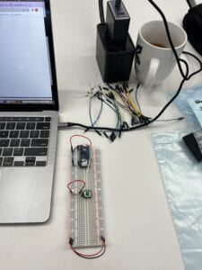
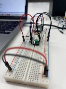
This lab seemed introductory enough, however some issues with the hardware caused it to drag on, soliciting help from three or four others, all to discover one of the wires needed replacing. Things started out smoothly with the basic setup of an Arduino Nano 33 IoT mounted to a solderless breadboard. I connected power to the +3V3 pin of the microcontroller and ground of the microcontroller to ground of the breadboard. I finished the circuit at the bottom of the breadboard connecting power on the left side to power on the right side then ground on the left side to ground on the right side.
Then I straddled a button across the two sides of the breadboard, connected its lower left leg to the D2 pin of the arduino and to a 220-ohm resistor, which is connected to ground. I connected the top left leg of the button to power.

Now, for the LEDs. I placed both LEDs into the right side of the breadboard, connecting their cathode (long, positive leg) to power in the righthand voltage bus and their anode (short, positive leg) to resistors, which connect to the D3 and D4 pins of the Arduino.

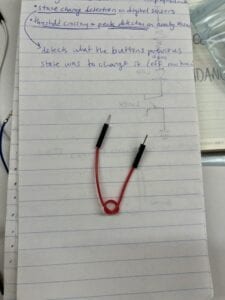
When I compiled the code from the lab, nothing worked:’). Dora and Rahim and Liyan Bing helped me troubleshoot by teaching me about Serial.println() and the Serial Monitor and how to isolate different aspects of the circuit to narrow down the source of the problem. We switched buttons twice, rearranged configurations, etc. Eventually, changing one of the wires solved the issue and the button began to control the lights.
Rahim also reminded me to use red wires for power, black wires for ground, and blue wires for connections. Thanks, Rahim!
The faulty wire that was preventing the circuit from flowing >:(. Put a knot in it so I know not to rely on it anymore.


Leave a Reply