Interaction Lab Final Project Individual Reflection
Project Title: Integrated Art – Tina & Wendy – Marcela Godoy
Conception and Design: Basically, this idea was originated from one of my random thoughts that whether arts can really be integrated with each other. I have been learning Calligraphy for more than 10 years since I was young. And my Calligraphy teacher always told me that different types of arts can be integrated since their origins are the same, especially for Calligraphy and traditional Chinese painting. However, I observed that there still kids like me, who are good at one of them but can hardly master the other one though paid great effort. That made me start to doubt the fact that my teacher told me. In fact, in the real world, we can see so many examples. Most of us may professionals in one of the art fields, but hardly can everyone become a master in all different kinds of fields. I believe it is true that all kinds of arts have the same origins and can be integrated. However, there are two other important factors for a person to be a master in one art, one is talent, the other is time and energy devoted to learning them. These factors are hampering us to become a performer in all different kinds of art. Therefore, I was thinking about if there would be any way that I can create a stage for people to perform different kinds of art forms, while at the same time, create a different art piece in another art form. With the knowledge that we have learned from the class, I learned how to use physical elements to detect sound and movements and display them on the screen with the use of Processing. Therefore, I started to consider creating a project for people to create a piece of drawing while singing and dancing on the stage. Previously, I thought it would be too hard for me to really track the movements of users accurately, so I wanted to use different cubes or a grid on the screen with “if sentences” to detect a rough position of the person. However, after sharing my idea with Wendy, she suggested I use the accurate live positions of the users to improve my project. Then, we formed a group and came up with three different ideas in all. Finally, after hearing Professor Marcela’s idea, we decided to conduct this project. However, we did meet with a lot of obstacles, for example, both Wendy’s and my computer had problems accessing the camera with Processing, which is an important part to test our code. Also, we found the coding really challenging us. What’s more, the setting up seemed also important and hard for us since it was hard to find a free place to test how the distance should be. Fortunately, we finally solved these problems and were able to continue and finish our project.
Since this idea came up due to my personal experience, the researches we did mostly were used to inspire the other two projects that we thought of. But, in the process of realizing our project, we did do a lot of researches, especially about how to track a specific object’s movement. Then, we found out that tracking a specific color may seem most possible and reachable for us. After many tries and learning from Internet resources, as well as some assistance from Professor Marcela, we finally were able to realize it.
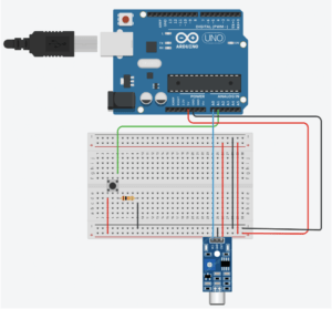
Also, we used Arduino and a loudness sensor to create a microphone to detect the users’ sound properties. By analyzing this data, we created different patterns of the painting brushes for each range of values. In that way, the users are able to use the dancing movement to determine the positions of the brush and use their singing voice to determine the kind of brush, which would finally become a piece of drawing.
However, in the user testing, we saw problems much more than the accuracy of our brush positions and the sensitiveness of our loudness sensor, and one of the most severe problems was that seldom could users even know what they were supposed to do to interact with the screen and camera. Therefore, to solve that problem, we recorded a piece of sound instructions and put it at the very beginning of the code so that it could trigger every time the project was operated.
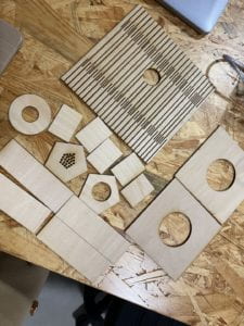
Fabrication and Production: Speaking of the fabrication, we designed a customized looking of our microphone, which is not exactly the same as the normal ones that we could see on the product market. Our design contains three different parts, a Hexagonal Column contains the loudness sensor, a rectangular contains our breadboard, and a cylinder contains only the wires. The three parts of the design are based on the wires we have and the elements we use. For the container of the loudness sensor, we make it a column instead of a cylinder because for the laser cut, cutting a cylinder means a lot of cutting stripes which may affect the stability and strength of the container. While for the holder, also the container of long wires, users’ hand feeling is the most important and it does not have to be that stable as the container of loudness sensor needs to be. And for the triangular part, we measure the size of the breadboard and designed it appropriately and accordingly. Then, we used the laser cutter to cut all of these parts. After several times of checking the circuit, we finally did the assembling of all elements. And the first time, we did not know what the problem was, but probably some wires touched each other in the process of our assembling, causing a short circuit. Therefore, we had to reassemble and assemble them again. This time we used hot glue in some places that have large parts that are exposed to the outside atmosphere. Then, we did the assemble again, and we succeeded.
For the whole process of producing our project, I have mentioned some important turning points in the previous part, therefore, I would like to give out a time list of the sequence of our steps below:
- decide the project and the detailed and complete interaction that will be used in this project.
- determine how we want the stage to be like
- lend things, including loudness sensor, projector, and the external camera, etc.
- do researches on the Internet and try coding by ourselves
- design the microphone, appoint for the laser cut and laser cut
- deal with the computer system problem and started to be able to use the camera, test our previous coding
- buy some additional stuff, like a pair of red gloves, and grey cotton for creating a clean background to avoid the interference of background-color
- try different patterns of the brushes
- prepare for the user testing
- revise our project based on the feedback we received in the user testing, such as adding a recording at the very beginning of each time’s operation
- try to write a code to directly track the red of the glove, however, it failed
- do the final assembly and set up
[Laser Cut Documentation]
Conclusions: The goal of our project is to create a stage for people to draw a painting when singing and dancing, as an experimental way in discovering some possible solutions to integrate different kinds of art forms.
Technical Documentation:
[Video Documentation]
First time to detect the object and draw track path
Try to use MPEG as the brush (just tried for fun at first)
Want to try if we can add some brushes into our previous code and make more interesting changes with the detected sound values change, but we fail. It was too unstable and changeable.
After a long time hard try, we still failed. Finally, we decided to try if the MPEG that we tried for fun before could work well.
First test: change the brightness of the MPEG accordingly with the note of the sound
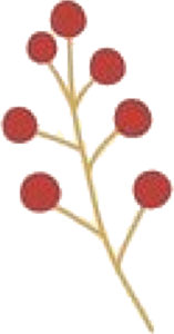
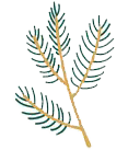
Then, we selected several symbolic and anesthetic pictures of Christmas elements:
We found the original picture from Pinterest, and use photoshop to create them more like brushes. Below are the finalized ones that we inserted into our Processing code:
User Test
Complete Final Version
[Code Documentation]
[Processing]
import processing.sound.*;
SoundFile sound;
// Example 16-11: Simple color tracking
import processing.serial.*;
PImage img;
PImage img2;
PImage img3;
PImage img4;
PImage img5;
PImage img6;
PImage img7;
PImage img8;
String myString = null;
Serial myPort;
//read multiple sensor values
int NUM_OF_VALUES = 2;   /** YOU MUST CHANGE THIS ACCORDING TO YOUR PROJECT **/
//sensorValue+previousValue
int[] sensorValues;
int preSensorValues1;
//video import--camera
import processing.video.*;
String[] cameras = Capture.list();
// Variable for capture device
Capture video;
PGraphics pg;
int sel = 0;
int closestX = 0;
int closestY = 0;
//previousValue
int pclosestX =0;
int pclosestY =0;
//use sound sensor value -- sensor1
float r;
float g;
float b;
//strokeWeight
float weight;
//sensor1Value
//int valueFromArduino;

// A variable for the color we are searching for.
color trackColor;

void setup() {
  //video.size()
  size(640, 480);
    setupSerial();
    sound = new SoundFile(this, "1.aiff");
    sound.play();

      img=loadImage("leaves0.png");
       img2=loadImage("leaves1.png");
       img3=loadImage("leaves2.png");
       img4=loadImage("leaves3.png");
       img5=loadImage("leaves4.png");
       img6=loadImage("leaves5.png");
       img7=loadImage("leaves6.png");
       img8=loadImage("leaves7.png");
      printArray(Serial.list());
  pg = createGraphics( width, height);
  video = new Capture(this, cameras[0]);

  video.start();
  // Start off tracking for red
  trackColor = color(255, 0, 0);
  colorMode(HSB,255);
}

void captureEvent(Capture video) {
  // Read image from the camera
  video.read();
}

void draw() {
 // trackColor = color(180, 0, 30);
 updateSerial();
  printArray(sensorValues);
  if (video.available()) {
    video.read();
  }
  //while ( myPort.available() > 0) {
  //  valueFromArduino = myPort.read();
  //}
  video.loadPixels();
  pushMatrix();
  translate(width, 0);
  scale(-1, 1);
  image(video, 0, 0);
  popMatrix();

  // Before we begin searching, the "world record" for closest color is set to a high number that is easy for the first pixel to beat.
  float worldRecord = 500;

  // XY coordinate of closest color

  // Begin loop to walk through every pixel
  for (int x = 0; x < video.width; x ++ ) {
    for (int y = 0; y < video.height; y ++ ) {
      int loc = x + y*video.width;
      // What is current color
      color currentColor = video.pixels[loc];
      float r1 = red(currentColor);
      float g1 = green(currentColor);
      float b1 = blue(currentColor);
      float r2 = red(trackColor);
      float g2 = green(trackColor);
      float b2 = blue(trackColor);
     // sensorValues[0] = int(map(sensorValues[0],200,400,0,255));
       r = sensorValues[0]/4;
       g = sensorValues[0]/2;
       b = 255-sensorValues[0]/3;
       //weight = sensorValues[0];
       //smooth the process between presensorValue and sensorValue
       //it doesn't work
       //for(int i = 1; i < abs(sensorValues[0]-preSensorValues1); i = i+5){
       //    r = sensorValues[0]*i;
       //    g = sensorValues[0]/i;
       //    b = 255-sensorValues[0];
       //    preSensorValues1=sensorValues[0];
       //}
       //sensorValues[0] = int(map(sensorValues[0],80,160,0,255));
      // Using euclidean distance to compare colors
      float d = dist(r1, g1, b1, r2, g2, b2); // We are using the dist( ) function to compare the current color with the color we are tracking.

      // If current color is more similar to tracked color than
      // closest color, save current location and current difference
      if (d < worldRecord) {
        worldRecord = d;
        closestX = x;
        closestY = y;
      }
    }
  }


  // We only consider the color found if its color distance is less than 10.
  // This threshold of 10 is arbitrary and you can adjust this number depending on how accurate you require the tracking to be.
  if (worldRecord < 10) {
    if (sensorValues[1]>0) {
    pg.beginDraw();
    pg.clear();
    pg.endDraw();
    }else{
    // Draw a circle at the tracked pixel
    //fill(trackColor);
    //strokeWeight(10);
    //noStroke();
    pg.beginDraw();
    //specifically what you draw
    pg.stroke(255);
    //pg.stroke(sensorValues[0]);
    //to not draw from the top left corner
    if (pclosestX == 0 && pclosestY ==0) {
      pg.point(closestX, closestY);
    } else {
      pushMatrix();
      //mirror
      pg.translate(width, 0);
      pg.scale(-1, 1);
      //change image color
      //pg.tint(sensorValues[0],150,150);
      //import and use image
      if (sensorValues[0]>-50&&sensorValues[0]<80) {
      pg.image(img,closestX,closestY,50,50);
      }
       if (sensorValues[0]>80&&sensorValues[0]<100) {
      pg.image(img2,closestX,closestY,50,50);
      }
      if (sensorValues[0]>100&&sensorValues[0]<120) {
      pg.image(img3,closestX,closestY,50,50);
      }
       if (sensorValues[0]>120&&sensorValues[0]<140) {
      pg.image(img4,closestX,closestY,50,50);
      }
      if (sensorValues[0]>140&&sensorValues[0]<180) {
      pg.image(img5,closestX,closestY,50,50);
      }
      if (sensorValues[0]>180&&sensorValues[0]<200) {
      pg.image(img6,closestX,closestY,50,50);
      }
      if (sensorValues[0]>200&&sensorValues[0]<240) {
      pg.image(img7,closestX,closestY,50,50);
      }
      if (sensorValues[0]>240&&sensorValues[0]<460) {
      pg.image(img8,closestX,closestY,50,50);
      }
      //pg.fill(r,g,b);
      //pg.stroke(sensorValues[0],150,150);
      //pg.noStroke();
      //pg.strokeWeight(5);
      //pg.line(closestX, closestY, pclosestX, pclosestY);
     //pg.circle(closestX, closestY,50);
      popMatrix();
    }
    pg.endDraw();
    }
    image( pg.get(0, 0, width, height), 0, 0);
    pclosestX = closestX;
    pclosestY = closestY;

}
}


  void setupSerial() {
  printArray(Serial.list());
  myPort = new Serial(this, Serial.list()[1], 115200);
  myPort.clear();
   myString = myPort.readStringUntil( 10 );  // 10 = '\n'  Linefeed in ASCII
  myString = null;

  sensorValues = new int[NUM_OF_VALUES];
}
void updateSerial() {
  while (myPort.available() > 0) {
    myString = myPort.readStringUntil( 10 ); // 10 = '\n'  Linefeed in ASCII
    if (myString != null) {
      String[] serialInArray = split(trim(myString), ",");
      if (serialInArray.length == NUM_OF_VALUES) {
        for (int i=0; i<serialInArray.length; i++) {
          sensorValues[i] = int(serialInArray[i]);
        }
      }
    }
  }
}

void mousePressed() {
// Save color where the mouse is clicked in trackColor variable
  int loc = mouseX + mouseY*video.width;
  trackColor = video.pixels[loc];
}
[Arduino]
Circuit-TinkerCad
#include "arduinoFFT.h"

arduinoFFT FFT = arduinoFFT(); /* Create FFT object */
/*
These values can be changed in order to evaluate the functions
*/
#define CHANNEL A0
const uint16_t samples = 128; //This value MUST ALWAYS be a power of 2
const double samplingFrequency = 100; //Hz, must be less than 10000 due to ADC

unsigned int sampling_period_us;
unsigned long microseconds;

/*
These are the input and output vectors
Input vectors receive computed results from FFT
*/
double vReal[samples];
double vImag[samples];

#define SCL_INDEX 0x00
#define SCL_TIME 0x01
#define SCL_FREQUENCY 0x02
#define SCL_PLOT 0x03

void setup()
{
  sampling_period_us = round(1000*(1.0/samplingFrequency));
  Serial.begin(115200);
  while(!Serial);
  Serial.println("Ready");
}

void loop()
{int sensor1 = analogRead(A0);
  int sensor2 = analogRead(A1);
  Serial.print(sensor1);
  Serial.print(",");  // put comma between sensor values
  Serial.print(sensor2);
   Serial.println();
  /*SAMPLING*/
  microseconds = micros();
  for(int i=0; i<samples; i++)
  {
      vReal[i] = analogRead(CHANNEL);
      vImag[i] = 0;
      while(micros() - microseconds < sampling_period_us){
        //empty loop
      }
      microseconds += sampling_period_us;
  }
  /* Print the results of the sampling according to time */
 // Serial.println("Data:");
  PrintVector(vReal, samples, SCL_TIME);
  FFT.Windowing(vReal, samples, FFT_WIN_TYP_HAMMING, FFT_FORWARD);  /* Weigh data */
 // Serial.println("Weighed data:");
  PrintVector(vReal, samples, SCL_TIME);
  FFT.Compute(vReal, vImag, samples, FFT_FORWARD); /* Compute FFT */
  //Serial.println("Computed Real values:");
  PrintVector(vReal, samples, SCL_INDEX);
  //Serial.println("Computed Imaginary values:");
  PrintVector(vImag, samples, SCL_INDEX);
  FFT.ComplexToMagnitude(vReal, vImag, samples); /* Compute magnitudes */
 // Serial.println("Computed magnitudes:");
  PrintVector(vReal, (samples >> 1), SCL_FREQUENCY);
  double x = FFT.MajorPeak (vReal, samples, samplingFrequency);
  //Serial.print(x);
 //if (analogRead(A0)>190){
 // Serial.print(",");
 Serial.println(x);
  int sensorValue = x;
  Serial.write(sensorValue);
  //}
 // Serial.print(analogRead(A0));
  //Serial.println("");

  // too fast communication might cause some latency in Processing
  // this delay resolves the issue.
  //delay(10);
}

void PrintVector(double *vData, uint16_t bufferSize, uint8_t scaleType)
{
  for (uint16_t i = 0; i < bufferSize; i++)
  {
    double abscissa;
    /* Print abscissa value */
    switch (scaleType)
    {
      case SCL_INDEX:
        abscissa = (i * 1.0);
  break;
      case SCL_TIME:
        abscissa = ((i * 1.0) / samplingFrequency);
  break;
      case SCL_FREQUENCY:
        abscissa = ((i * 1.0 * samplingFrequency) / samples);
  break;
    }
    //Serial.print(abscissa, 6);
    //if(scaleType==SCL_FREQUENCY)
     // Serial.print("Hz");
    //Serial.print(" ");
    //Serial.println(vData[i], 4);
  }
  //Serial.println();
  //delay(10);
}






Leave a Reply