11/23
Fall Break no Class
Assignments for next week
-
- Project 02 Critical Wearable (final) bring supplies to work in class.
- Reading 08: Heather Suzanne Woods, “Asking more of Siri and Alexa” (last reading!)
Fall Break no Class
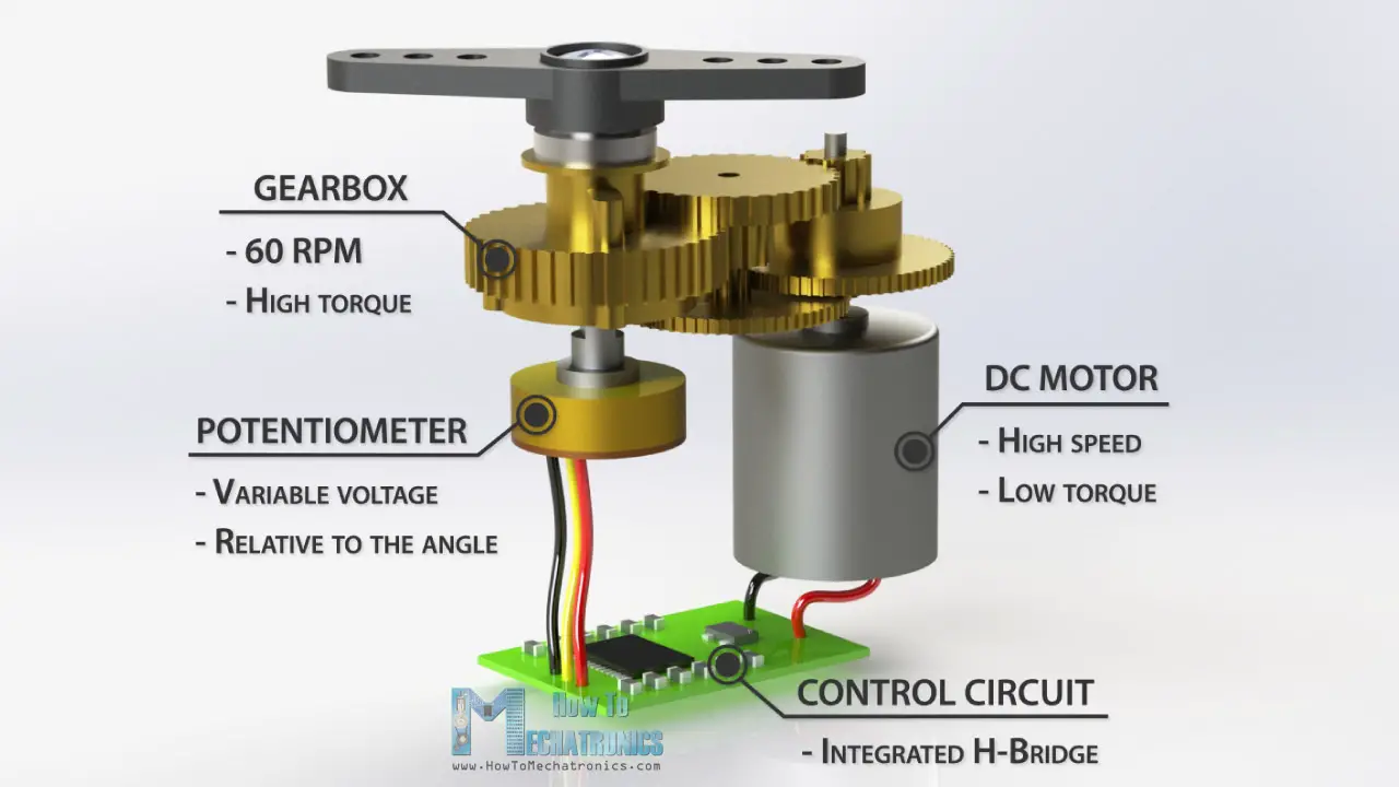
As you may recall from our motor lesson in week 3 , Servo motors have DC motors inside them, and an additional control circuit that allows us to connect them to Arduino. 
Outside of a Servo, DC motors should not be connected to Arduino directly, and should instead be connected to a motor control circuit, like an H-Bridge, which lets you control the direction of the motor (forward/backward).
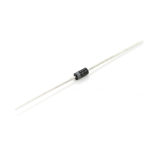
An easier motor control circuit to use with Arduino, consists of an NPN transistor, a diode, and a separate battery pack to power you motor. It allows you to turn your motor on/off, but not control the direction.


You can jump to testing the circuit in Step 02, using the vibration motor that came in your Wearables kit. However, you’re also welcome to salvage a DC motor from electronics you may have around the house. Lots of consumer electronics have motors: printers, some cameras, toys, plug-in scent releasers, small fans etc.
Remember we have a small battery pack so your motor will only be getting 4.8V. Large electronic junk (A/C, washing machine, etc.) is not suitable for this exercise.


Remember the BOM for all our supplies can be found on the syllabus. Look up the transistor we have, and locate the data sheet. What pin number is emitter, base and collector? These can be different on different transistors.
1. Connect the Arduino ground (gnd) to a ground rail on the breadboard (blue)
2. Connect both sides of the ground on the breadboard to each other
3. Connect the battery pack to one side of the breadboard (power and ground)
4. The NPN transistor has an emitter, base, collector. The emitter (left pin) is connected to ground directly. The base (middle pin) is connected to a digital pin on the Arduino (pin 6 in image). The collector (right) is connected to negative(-) of the motor, and one side of a diode (with the stripe). The other side of the diode is connected to ground.
5. The remaining motor pin is connected to the power rail of the battery pack. If you are using a motor that has positive and negative marked, this should be the positive wire. (If motor is not marked, usually reversing power/gnd will just change direction.)
Double check your wiring.
Copy and paste the test code into a new Arduino sketch, and upload it to check your circuit. The motor should turn on and off intermittently:
int Motor=6;
void setup() {

pinMode(Motor,OUTPUT);

Serial.begin(9600);

}
void loop() {
digitalWrite(Motor, HIGH); // turn the motor on (HIGH is the voltage level)

delay(3000); // wait for 3 seconds

Serial.println("motor on"); //for debugging

digitalWrite(Motor, LOW); // turn the motor off by making the voltage LOW

delay(3000); // wait for 3 seconds

Serial.println("motor off"); //for debugging

}
if you try to write code that uses a lot of delays and is also looking for sensor input, it will not be super reliable, because the Arduino is essentially asleep during a delay, and won’t detect the sensor values. you can work instead with Arduino’s built in timer “millis().” Two ways to do this are through if statements or “do{} while()” loops.
int Motor=12;

unsigned long lastMilli;

int interval;
void setup() {

pinMode(Motor,OUTPUT);

Serial.begin(9600);

lastMilli = millis();

}
void loop() {

interval = millis()-lastMilli;

Serial.println(interval);

if(interval < 3000){ digitalWrite(Motor, LOW);
Serial.println("motor off");
}
else if((interval >= 3000) && (interval <6000))
{ digitalWrite(Motor, HIGH);

Serial.println("motor on");
}
if(interval>=6000){

Serial.println("RESET");

delay(500);

lastMilli = millis();

}

}
DO WHILE
int Motor=12;

unsigned long lastMilli;

int interval;
void setup() {

pinMode(Motor,OUTPUT);

Serial.begin(9600);

lastMilli = millis();

}
void loop() {

do{

digitalWrite(Motor, LOW);

Serial.println("motor off");

interval = millis()-lastMilli;

Serial.println(interval);

}
while(interval < 3000);
do{

digitalWrite(Motor, HIGH);
Serial.println("motor on");
interval = millis()-lastMilli;

Serial.println(interval);

} while((interval >= 3000) && (interval <6000));
Serial.println("RESET");

lastMilli = millis();

}
The below instructions show how to introduce a sound sensor, so you can make a clap on/ clap off motor. (Or scream activated, like this project).
You can adapt this code to the circuit playground to use the onboard sound sensor there, or use a different analog sensor to control your vibration motor with Arduino Nano.
1. Connect the 3.3V on Arduino or CP to power on one side of the breadboard. (Opposite the battery pack)
2. Connect the “out” pin on the sound sensor to pin 10 on the Arduino. Connect the GND pin the ground rail on the breadboard. Connect the VCC pin to the power rail that is connected to Arduino. (Not the batteries! The batteries will output too much power).

Copy and paste the test code into a new Arduino sketch, and upload it to check your circuit. The motor should turn on if you clap your hands loudly in front of the sensor.
int Motor = 6;

int soundSensor = 10;

boolean SoundStatus = false;
void setup() {

pinMode(soundSensor, INPUT);

pinMode(Motor, OUTPUT);

Serial.begin(9600);

}
void loop() {
int SensorData = digitalRead(soundSensor);

Serial.println("Sound level= ");

Serial.println(SensorData);

if (SensorData == 1) {
if (SoundStatus == false) {

SoundStatus = true;

digitalWrite(Motor, HIGH);

delay(500); // increase this number to have motor run longer

}
else {

SoundStatus = false;

digitalWrite(Motor, LOW);

delay(500); // increase this number for a longer pause
}

}

}
You may need to adjust the sensitivity of the sensor, by adjusting the small screw on the front. Do this while checking the levels on Serial Monitor.

Project 02: Critical Wearable -25%
Design and make a wearable that critically engages with one of the topics below. If you would like to expand on an idea you have begun in an earlier portion of the class, such as in an assignment or project, you are welcome to do so, but Version 2 should show significant growth from the first iteration. Your final design should be tested, (ideally with your target population/site but you can also use yourself as a stand-in) and documented through images and/or video. Documentation should be uploaded to Discord in advance of presentation. Documentation quality will be a key part of assessment. Real time demos are also appreciated. Be prepared to explain your concept and process (with images) in your presentation.
Recommended Concepts (I am happy to discuss additions to this list):
Sketch due to Discord: 11/16
Final due: 12/07
Assignment 05: Wearable for non-Human Interaction- 8%
Design a wearable for something other than a human: an animal, plant, building, infrastructure, robot, or ghost—the goal of this project is to consider technology design from a lens that is less human-centered.
Alternatively, you can design something wearable for a human, that is designed to improve the wearer’s relationship, or create a dialogue with, something non-human, but your design should center non-human needs.
Your final piece must include some aspect of a physical prototype, but you may “wizard-of-oz” aspects of it if your design is too speculative to fully function.
Due: 11/16
Assignment 04: Soft Interface -8%
Produce a novel soft interface such as a soft switch, pressure pad, or touch sensor through use of e-textile materials (conductive nylon tape, conductive thread, conductive fabric, copper tape, etc.) Your switch can be part of a simple circuit or it can be read with a microcontroller.
Post an image or short video to Discord #assignment04 and be prepared to present in class.
Teamwork welcome.
Due 11/09