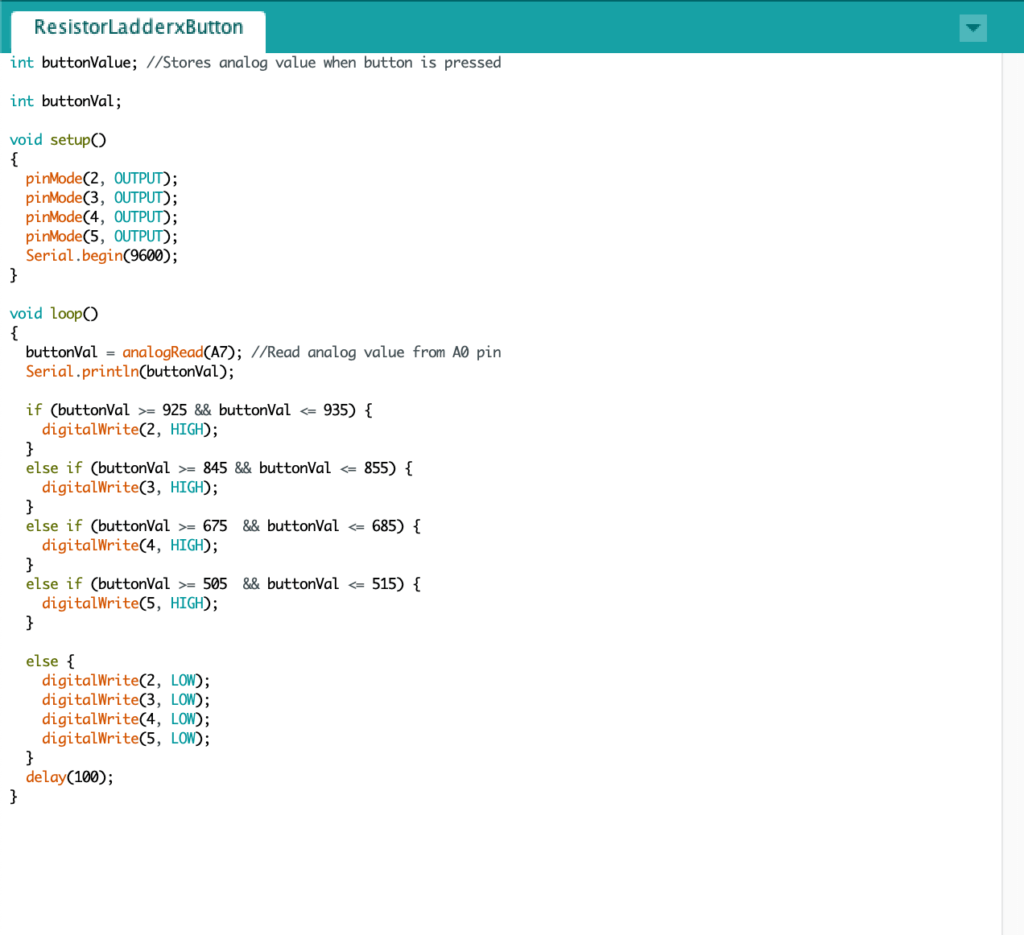
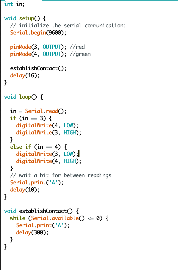
Some so-so soldering (re-soldered x1 because I wired things incorrectly without realizing. . . x1 more time when things went wrong and I thought soldering was the issue but it wasn’t — it was actually the analog values in the code for some reason that changed but when I use a different test code with the old analog range to determine which button is pressed, the old values work just fine. Being able to get better at soldering made the repeat worth it though.)
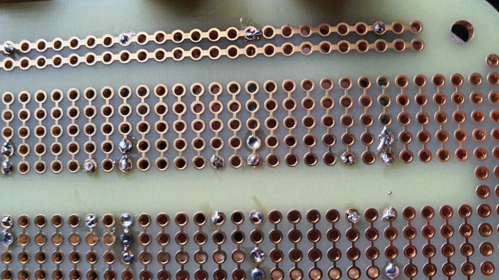
I tested the soldered circuit and it worked.
But at some point, after a lot of building progress it stopped working (explanation above) so I had to troubleshoot (yay for tape — no yay for me because my theory about what wasn’t working was way off).
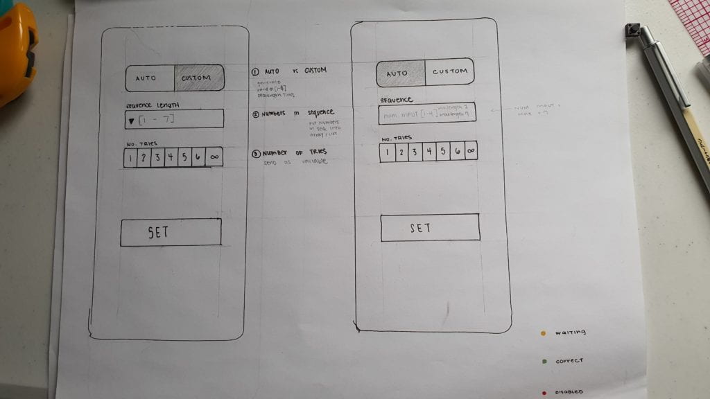
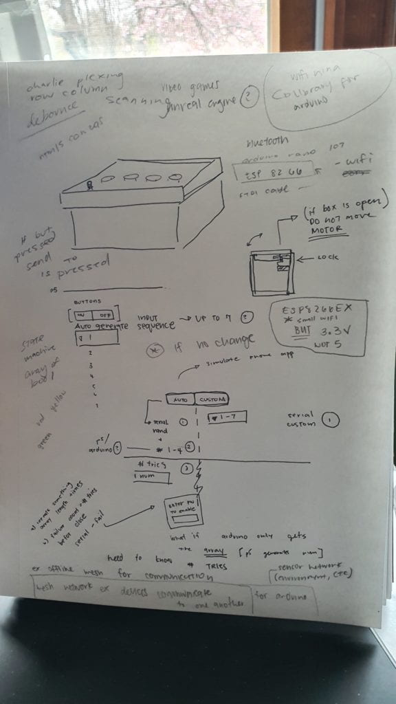
I then decided to map out the components and figure out how I should go about building the box.
I started with the front with the interface for the buttons and the lights along with the surface where most of my components would reside.
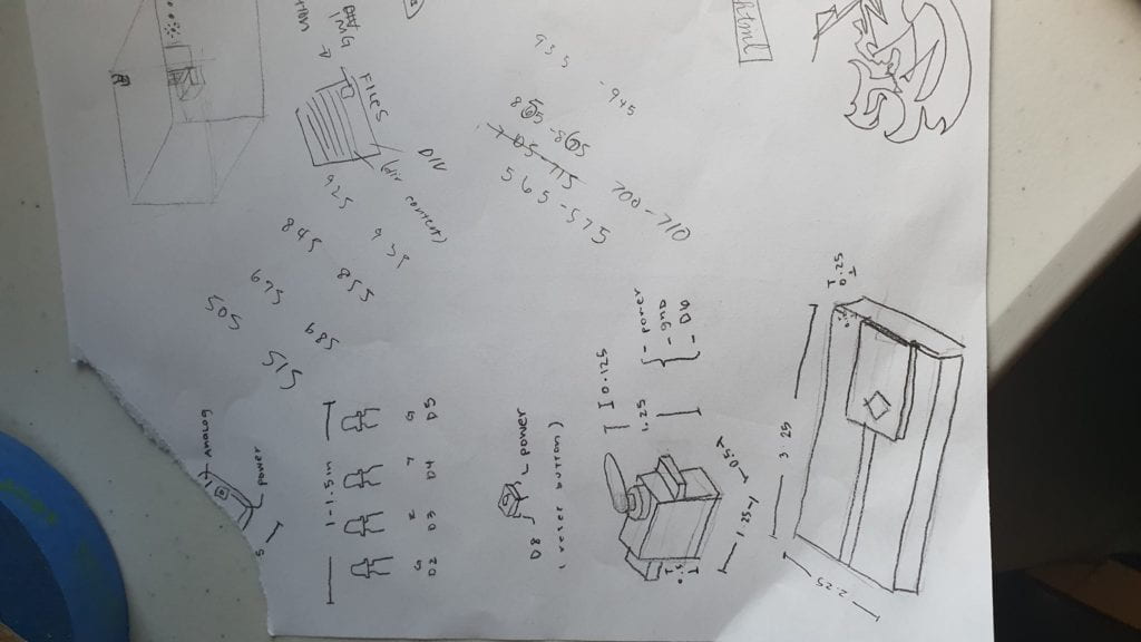
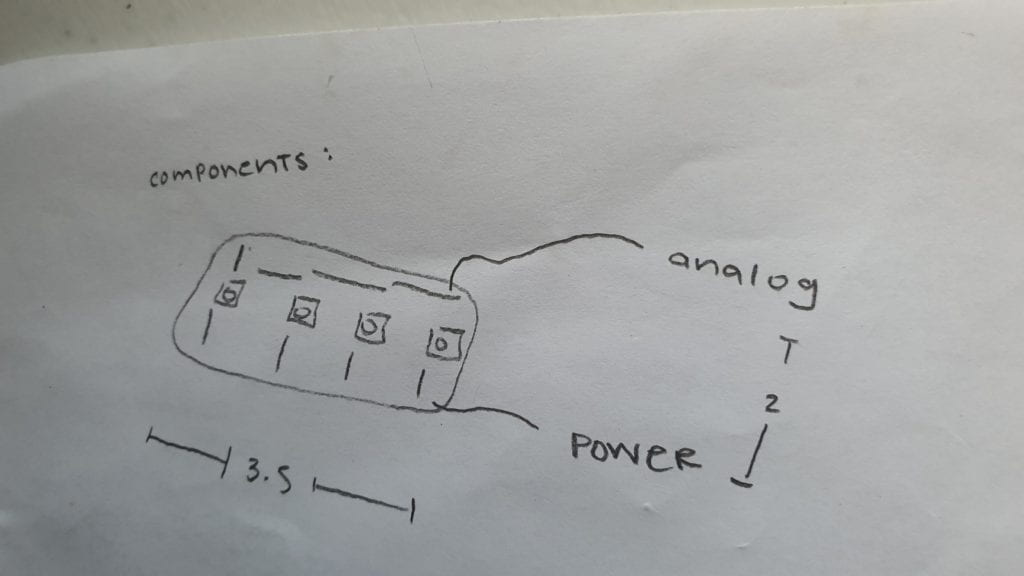
^replacement for torn corner
I then prototyped possibilities for the way the buttons would be pressed:
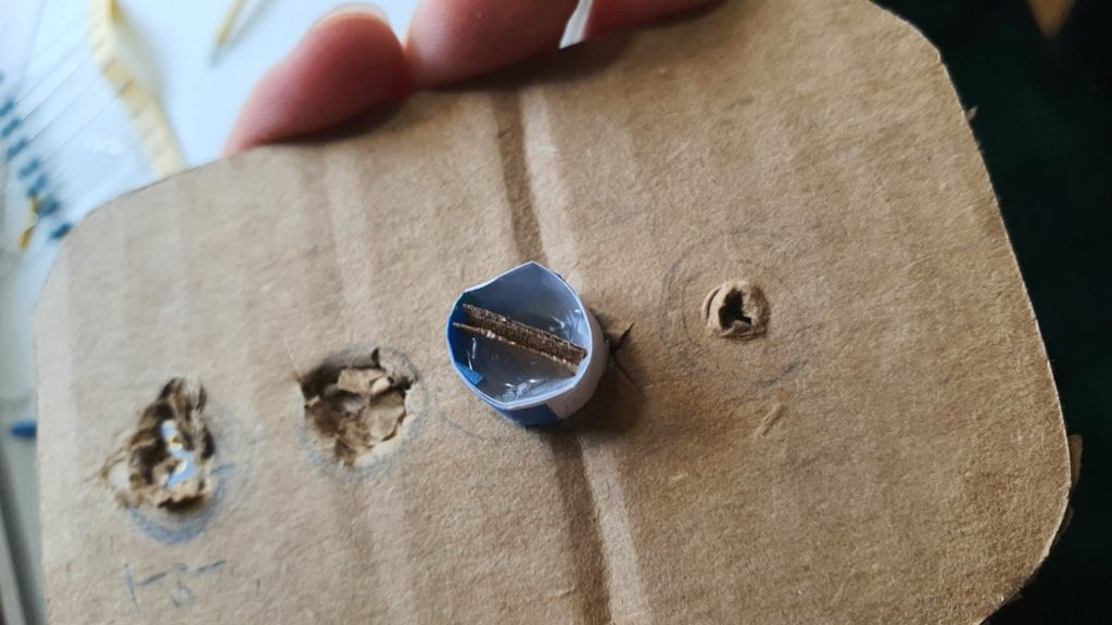
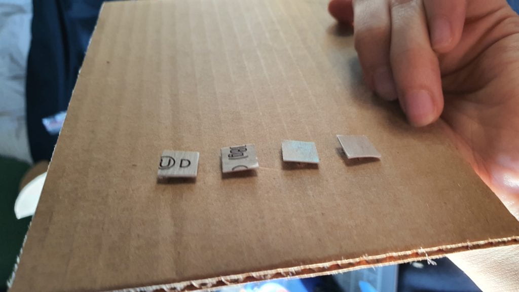
and arranged the inside components (featuring gluing, ungluing, unsoldering, things breaking, and things being fixed.
Important things I would want to remember:
Know which to troubleshoot — code vs hardware
Insulate things (I tried to separate the LED wires with tape but initially did so poorly so currents got mixed)
After troubleshooting and further assembling this, I tested my would-be lock system by taping my lock to the servo and then gluing it afterward. To my surprise, it worked well, especially once everything was glued together.
Possible future iterations:
Connect to the internet
Store data (EEPROM? — have to learn ore about this)
Add other stuff!!!
Figure out the puzzle circuit thing (framed not as a box but maybe as a children’s toy)
Experiment with ESP8266 and see if it’s possible to make small an emergency key lockbox that can be unlocked via phone x password or phone/password just coz it might be useful.
