Challenge 1 – Week 5
Week 5: Utilizing your Sketches and Models for CAD
Unnecessary Inventions and Whimsical Devices
For this week, the focus of the Challenge was to begin developing A Computer Aided Design model of the product that we have so far been developing through sketches and physical prototypes. For this, I used Fusion 360 software to recreate a digital version of my product, basing measurements and style components on the elements of the previously developed solid model figure.
Concept:
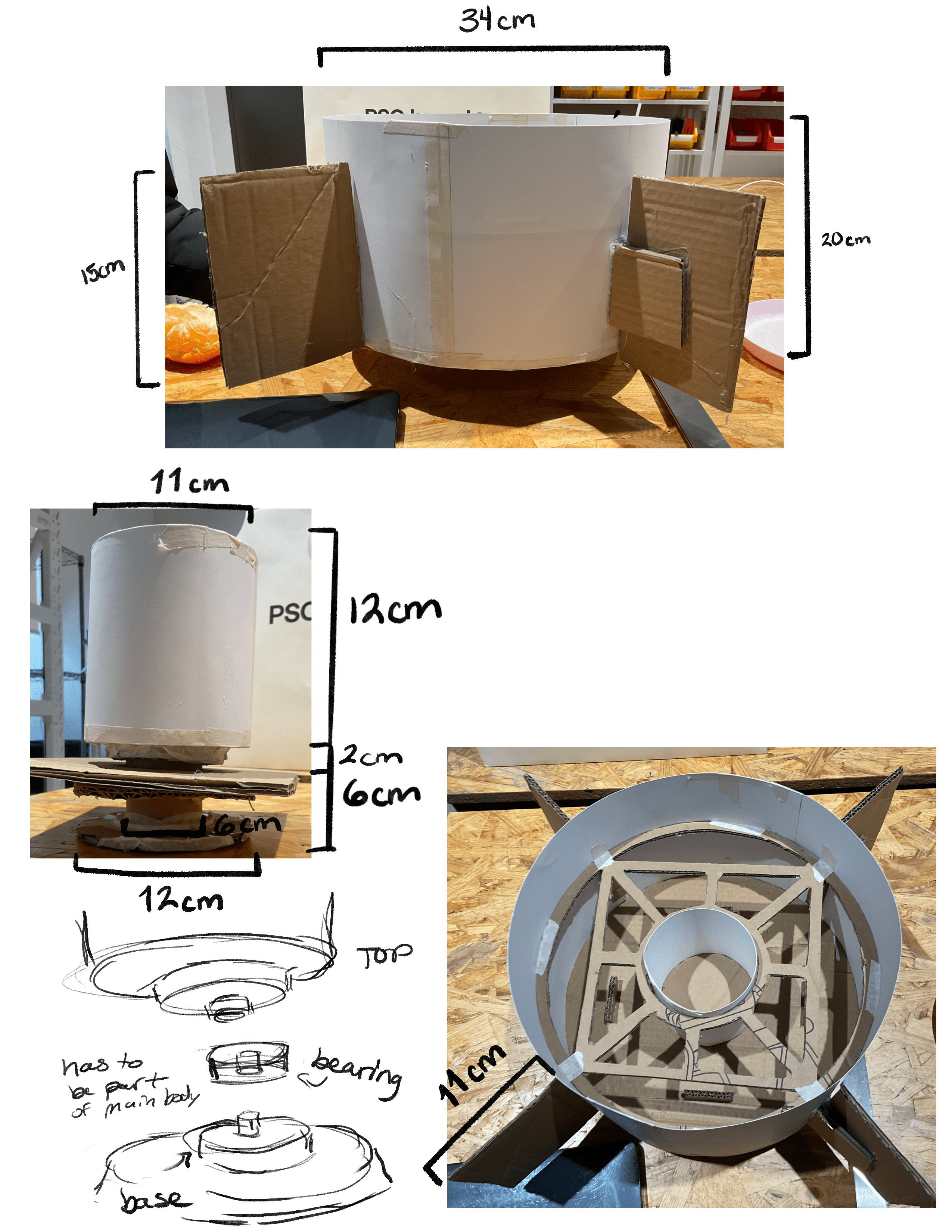
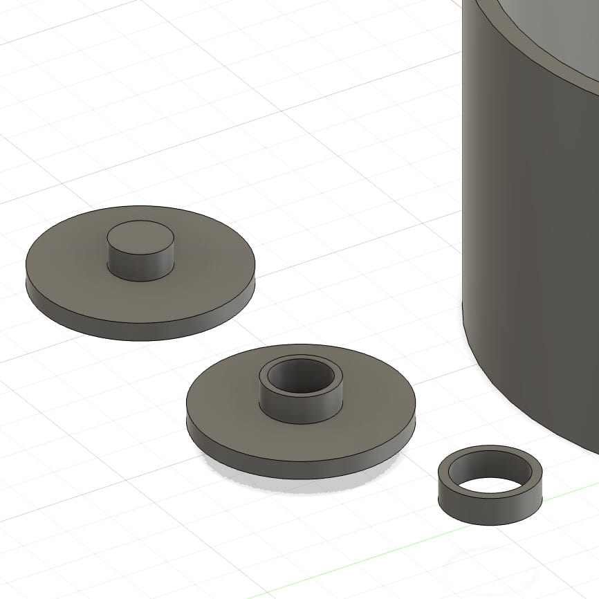
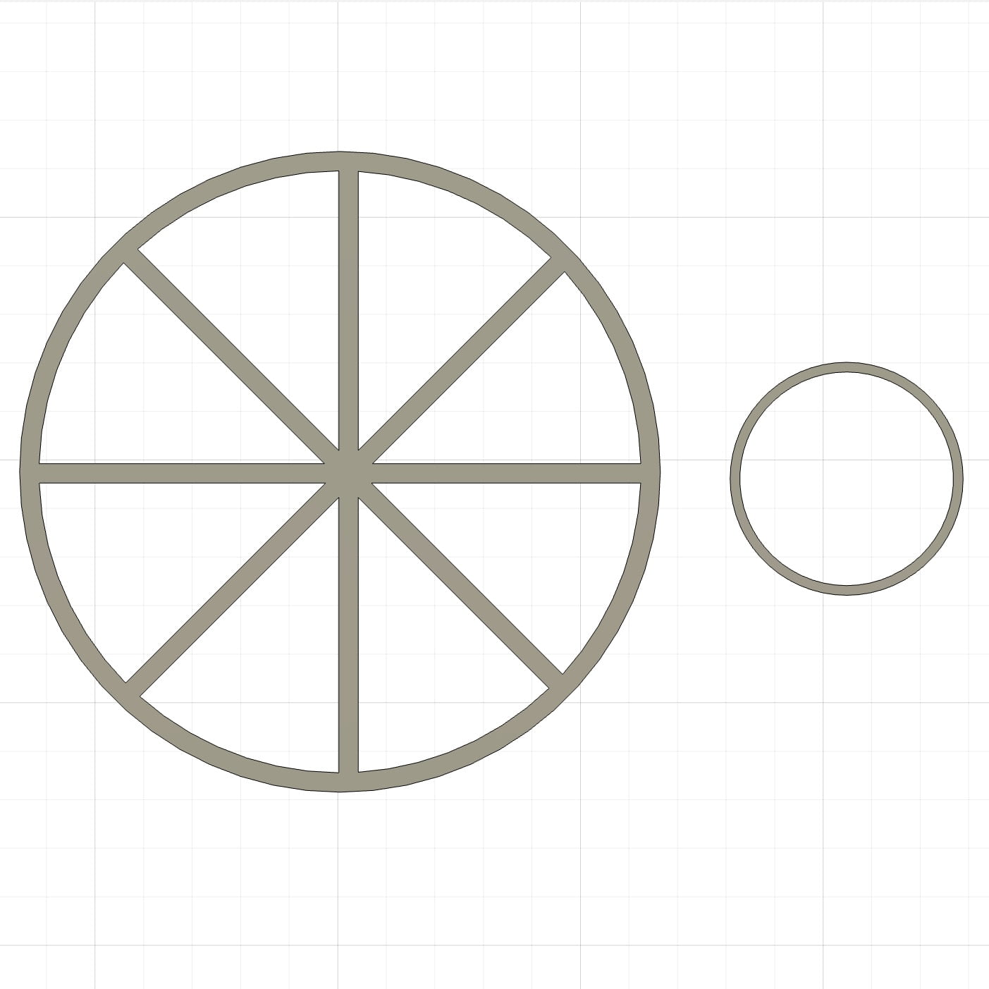
Still following my primary idea and sketches, in this step I also decided to go further and delve deeper into my original concept by redesigning some elements of the device. Besides altering the measurements and dimensions of certain components, the main change to the machine had to do with the gears and bearings. These pieces are responsible for allowing the separate areas of the product to move and spin smoothly. As one of the main contributors to the challenges that I faced during the physical model’s assembly process, I wanted to place extra focus on these when beginning the CAD model. However, quickly into the development process I realized that the original prototype’s bearing design was very bulky and weak. As a result, my first step was to come up with a new design fro those components that would enhance the model. For this, I ended up choosing a three piece system where the upper and lower sections could attach and detach from one another, while simultaneously allowing for free movement of the center piece. The machine’s main body would then connect to the small center piece, and rest between the two bearings, granting more free and frictionless movement.
Building Process:
1) Software Tools Used:
-
-
- Create
- Cylinder (create round shapes)
- Box (create angled shapes)
- Move/Copy (rearrange objects and copy/paste)
- I relied heavily on this tool to assemble, move, reorient, and duplicate pieces. Although at first it was a bit challenging to get a clear understanding of how the feature functioned, after some experimenting it became a straightforward and an essential aid
- Modify
- Combine (to unite separate figures)
- Chamber (to bevel edges of a surface)
- This tool was very helpful with both the technological and visual components of the design. With the Modify tool’s help I smoothed out edges brought together individual sections into singular and cohesive forms.
- Create Sketch (Isolate and edit components of a figure)
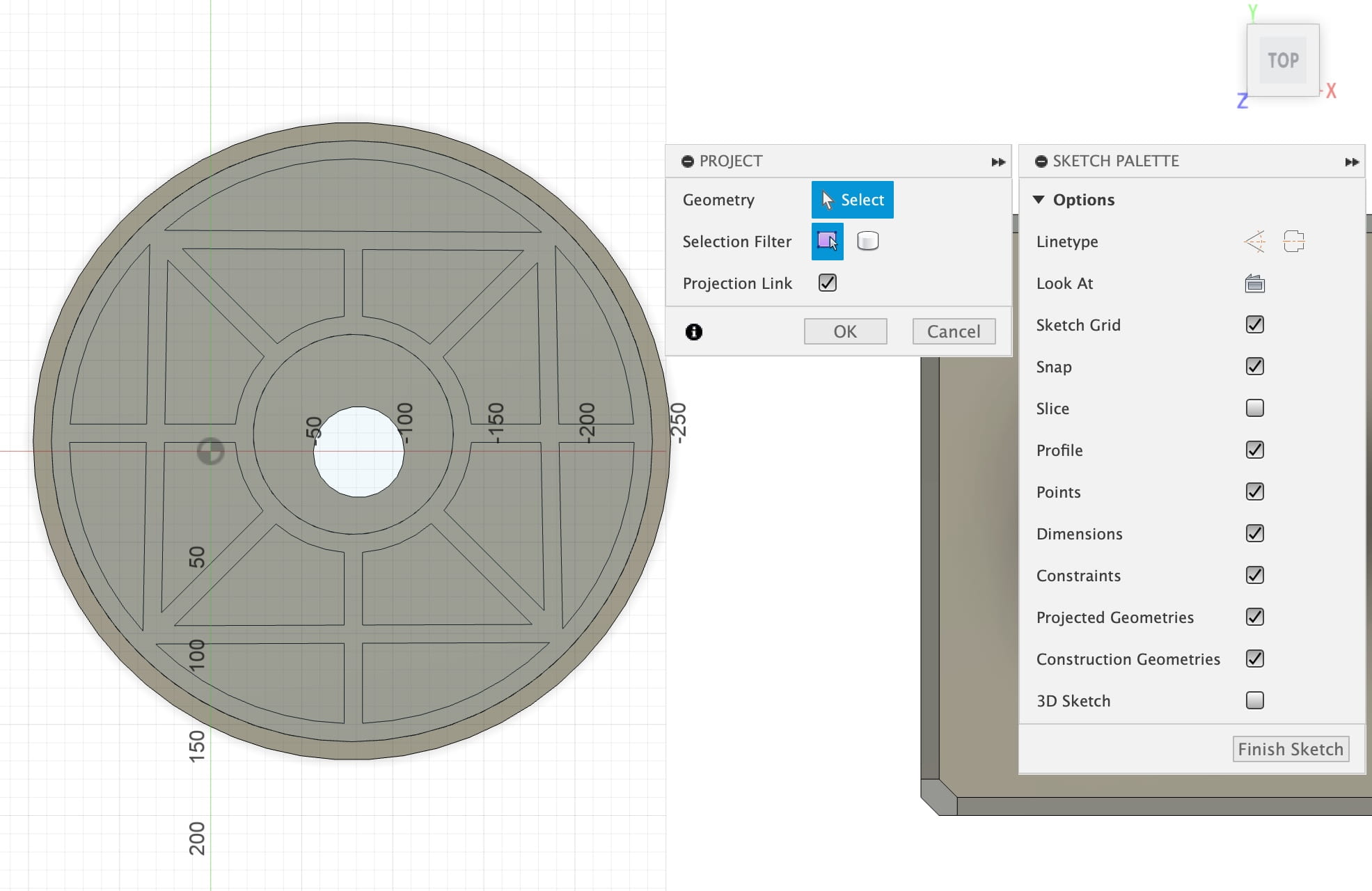
- As I cut out unnecessary aspects of shapes, using the Sketch selection to target and refine specific regions proved to be highly effective
- Create
-
2) Building CAD Model:
- Process video:
- Bearings:
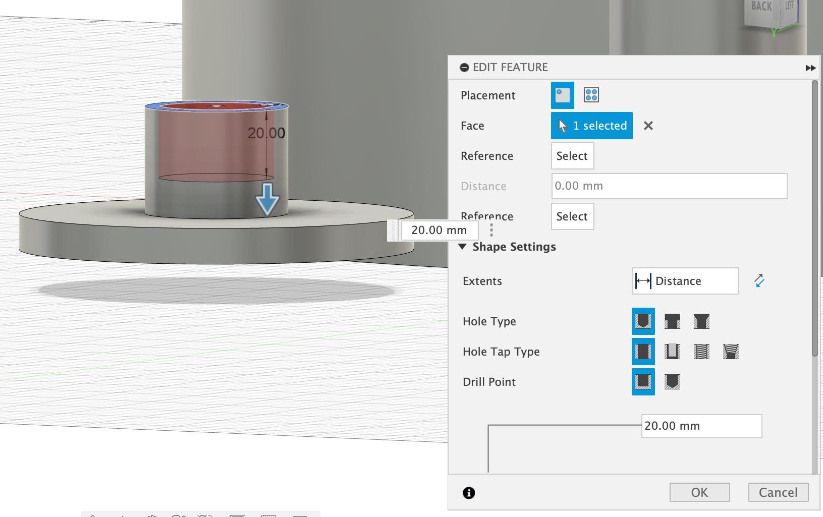
- The bearings faced the most changes, but in the end it became one of the strongest components of the design. Looking more into how spinning products are constructed, I decided to follow the example of machines such as the fidget spinner. Taking what I learned from close observation of the product blueprints, I altered and applied similar ideas to my own design. Ultimately after much trial and error, I found an effective solution that worked well with my product and addressed the worries I held. Furthermore, I also ended up adding another layer base to the bottom bearing to ensure that the machine is well balanced, also meaning it will be less likely to move or tip over when used.
- The Rack:
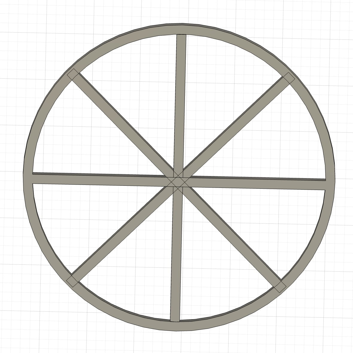
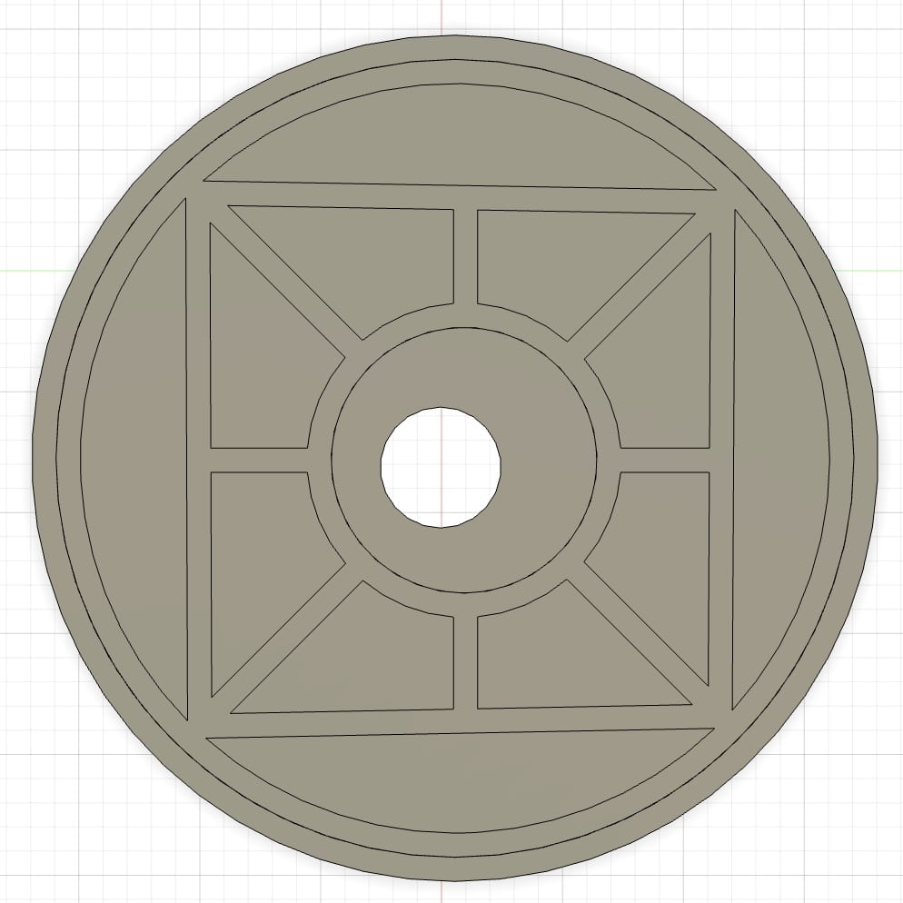
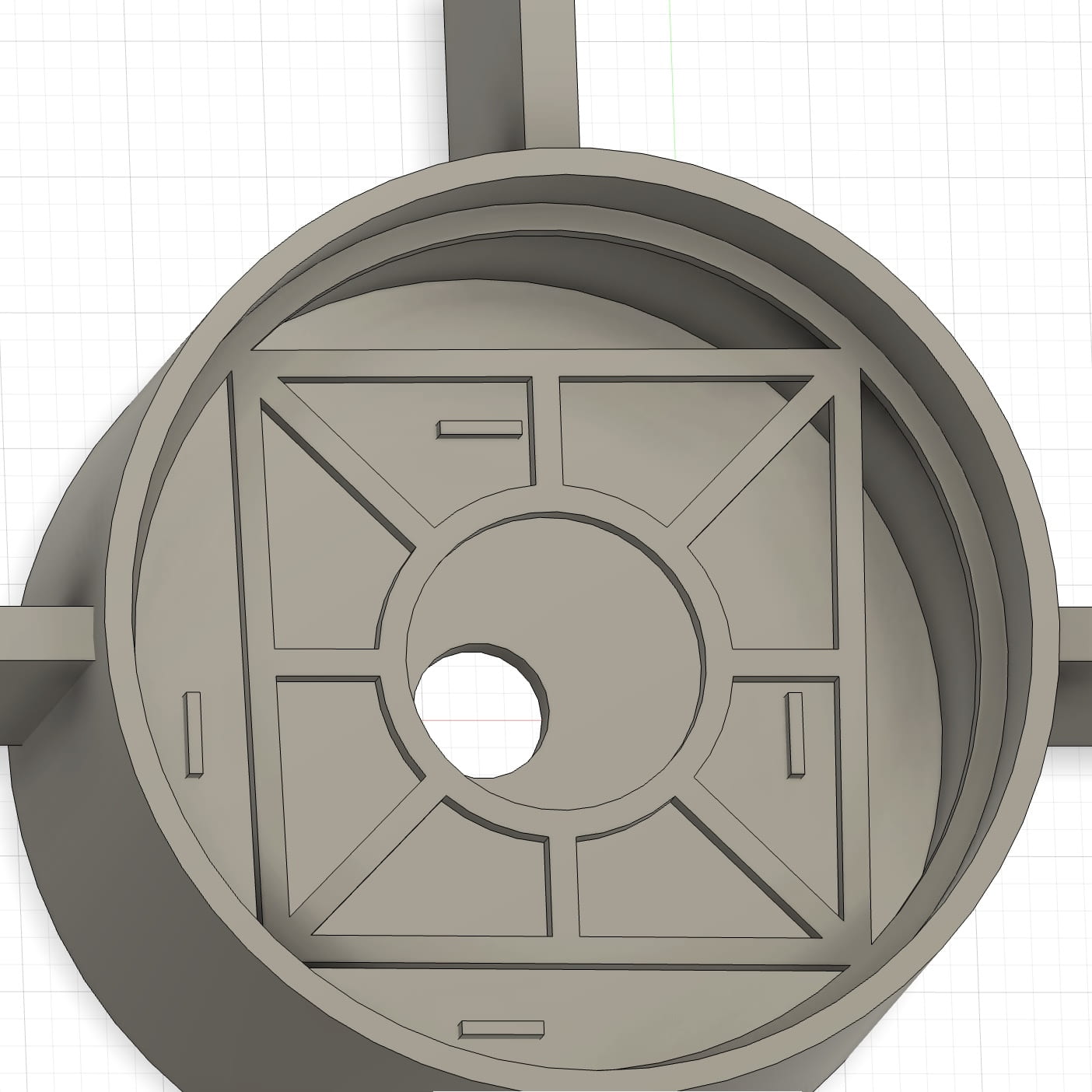
- My main focus with the rack was following the design of my prototype and sketches. However, because the details are so intricate, there were issues with the angle and measurements of some components. For example, the middle circle is off center and the rack is not equally parallel on all sides. Even though it is not too noticeable and doesn’t lead to any major problems, there were still some consequences to this mistake. When forming the spaces and eliminating unwanted pieces, I had to be more delicate and precise due to minor but present inconsistencies. Other than that, there were overall no major issues.
- Body and attachments:
- Finally, by utilizing the tools available I put together the various elements of the body, finalizing the CAD model. Again, despite some small mismatches in certain areas, the general design stayed loyal and consistent with my prior sketches and prototypes, while also making some much needed positive improvements along the way.
Results and Conclusion:

All in all, I am very satisfied with the results of my digital model. Although this was my first time using Fusion 360 or any form of 3D modeling, I believe the program is very intuitive and user friendly. Being able to visualize something in a 3D space but digitally simplifies some elements of the development process, and helps bring light to new methods of resolution to physically challenging issues. I was able to fix a lot of the mistakes that came up during the previous weeks prototype assembly through the software tools available on Fusion 360. Nevertheless, measurements can always be more accurate, and as I proceed I will work to make sure all the components of my project are effective and functional. With more practice and exploration, I can see myself relying on this CAD tools for projects in the future.
