Categories
Interaction Lab

Recitation 7

Task 1 & Task 2

In task 1 and task 2, I checked the download of the library and used the example to make sure the NeoPixel Led strip worked correctly. In the code of task 2, I can input the number to the monitor and make the LED light according to the order and color I entered.

Task 3 & Task 4

Combining the given code in task 1 and task 2, the NeoPixel Led strip can change color randomly with the mouse’s drag and click. At the same time, the music I chose was played. Then I struggled with how to make the color of the NeoPixel Led strip change with the music’s volume. I tried to modify the code, letting the number of led light-emitting can be controlled by the volume of music, and adding random in colors to make Led strip change more dynamic and ornamental.

With the help of the professor and partner, I found a way to control the light and fade of LEDs better by using “if” and “for”. If the volume is higher than before, the lit LEDs will keep their previous colors and the newly added LEDs will show random colors. If the volume is lower than before, the LEDs which show the volume higher at the moment will fade. 

The only regret is that I didn’t have the time and could not understand the “FFT analysis” code in Task 4 to integrate it into my code😱

The code:

/* This is a code example for Processing, to be used on Recitation 7
 You need to have installed the SerialRecord library.
 
 Interaction Lab
 IMA NYU Shanghai
 2022 Fall
 */
import processing.sound.*;
int pre_n=0;
import processing.serial.*;
import osteele.processing.SerialRecord.*;

SoundFile sample;
Amplitude analysis;

Serial serialPort;
SerialRecord serialRecord;

int W;         //width of the tiles
int NUM = 60;  //amount of pixels
int[] r = new int[NUM]; //red of each tile
int[] g = new int[NUM]; //red of each tile
int[] b = new int[NUM]; //red of each tile

void setup() {
  size(640, 480);

  // load and play a sound file in a loop
  sample = new SoundFile(this, "Feryquitous F9 - Monochrome Re.Surgence.mp3");
  sample.loop();

  // create the Amplitude analysis object
  analysis = new Amplitude(this);
  // analyze the playing sound file
  analysis.input(sample);

  printArray(Serial.list());
  String serialPortName = SerialUtils.findArduinoPort();
  serialPort = new Serial(this, "/dev/cu.usbmodem1101", 9600);
  serialRecord = new SerialRecord(this, serialPort, 4);
  serialRecord.logToCanvas(false);
  rectMode(CENTER);

  /*for (int i=0; i < NUM; i++) {
   serialRecord.values[0] = i;     // which pixel we change (0-59)
   serialRecord.values[1] = 0;  // how much red (0-255)
   serialRecord.values[2] = 0;  // how much green (0-255)
   serialRecord.values[3] = 0;  // how much blue (0-255)
   serialRecord.send();            // send it!
   }*/
}

void draw() {
  println(analysis.analyze());
  noStroke();
  for (int i=0; i<height; i++) {
    float b = map(i, 0, -height, 100, 255);
    stroke(0, 0, b);
    line(0, i, width, i);
  }
  fill(255, 100);

  // analyze the audio for its volume level
  float volume = analysis.analyze();

  // volume is a number between 0.0 and 1.0
  // map the volume value to a useful scale
  float vol = map(volume, 0, 1, 0, 60);
  // draw a circle based on the microphone amplitude (volume)
  circle(width/2, height/2, vol);

  int n=floor(vol);
  println(n);

 if (n>pre_n) {
    for (int i=pre_n; i<n; i ++) {

      r[n] = floor(random(0, 255));
      g[n] = floor(random(100, 255));
      b[n] = floor(random(160, 255));

      serialRecord.values[0] = i;     // which pixel we change (0-59)
      serialRecord.values[1] = r[i];  // how much red (0-255)
      serialRecord.values[2] = g[i];  // how much green (0-255)
      serialRecord.values[3] = b[i];  // how much blue (0-255)
      serialRecord.send();            // send it!
    }
  }
  if (n<pre_n) {
    for (int j=pre_n; j>n; j--) {
      serialRecord.values[0] = j;     // which pixel we change (0-59)
      serialRecord.values[1] = 0;  // how much red (0-255)
      serialRecord.values[2] = 0;  // how much green (0-255)
      serialRecord.values[3] = 0;  // how much blue (0-255)
      serialRecord.send();            // send it!
    }
  }
pre_n = n;
  
}

The video:

Categories
Interaction Lab

Recitation 6

I learned some new functions from examples such as making the ellipse move and leave track (which will disappear later) by constantly overlaying a big rectangle filled with background color, and letting the ellipse “bounce” to change its direction. Also, I tried to use some new code like “angle” and “translate” rotate” to make an eye that is “looking” at the mouse. It’s surprising that I can add some mathematical symbols into the code like “arctan” sin” cos”.

The poster:


The code:

float beginX = 0;
float endX = 1024;
float distX;
float x = 0;
float y = 0;
float step = 0.015;
float c = 0.0;
int i = 0;
float angle=0.0;

int rad = 60;
float xpos, ypos;

float xspeed = 10.0;
float yspeed = 10.0;

int xdirection = 1;
int ydirection = 1;
PFont myFont;

void setup() {
  size(1024, 768);
  background(0);
  distX = endX - beginX;
  xpos = random(0, width);
  ypos = 700;

  String[] fontList = PFont.list();
  printArray(fontList);
  myFont = createFont("BMJUAOTF", 32);
  textFont(myFont);
}

void draw() {

  noStroke();
  fill(0, 15);
  rect(0, 0, width, height);

  c += step;
  x = beginX + (c * distX);
  y = 1024 - (c * distX);

  xpos = xpos + ( xspeed * xdirection );
  ypos = ypos + ( yspeed * ydirection );

  if (xpos > width-rad || xpos < rad) {
    xdirection *= -1;
  }
  if (ypos > height-rad || ypos < rad) {
    ydirection *= -1;
  }

  ellipse(xpos, ypos, rad, rad);

  noStroke();
  fill(#FF4BD2); //red
  ellipse(x, height/2-150, 100, 100);
  fill(#FEFF34); //yellow
  ellipse(y, height/2, 100, 100);
  fill(#29FFFD); //blue
  ellipse(x, height/2+150, 100, 100);
  fill(#7E83FF, 100);
  ellipse(random(0, 1024), random(0, 768), 100, 100);
  fill(#69FF62);//green
  ellipse(xpos, ypos, 100, 100);


  if (x > 1024) {
    c = 0.0;
    beginX = 0;
    x=0;
    y=0;
  }

  push();
  noFill(); //rect
  stroke(random(0, 255));
  strokeWeight(6);
  rectMode(CENTER);
  rect(width/2-10, height/2+30, 350, 240);
  pop();

  fill(random(0, 255)); //text
  textSize(196);
  textAlign(CENTER, CENTER);
  text("IMA", width/2, height/2);

  noFill();
  stroke(#E5E286);
  strokeWeight(8);
  beginShape();
  curveVertex(width/2-100, 125);
  curveVertex(width/2-100, 125);
  curveVertex(width/2, 125-50);
  curveVertex(width/2+100, 125);
  curveVertex(width/2+100, 125);
  endShape();
  beginShape();
  curveVertex(width/2-100, 125);
  curveVertex(width/2-100, 125);
  curveVertex(width/2, 125+50);
  curveVertex(width/2+100, 125);
  curveVertex(width/2+100, 125);
  endShape();


  strokeWeight(12);
  noFill();
  ellipse(width/2, 125, 95, 95);
  angle=atan2(mouseY-150, mouseX-width/2);
  translate(width/2, 125);
  rotate(angle);
  fill(255);
  noStroke();
  ellipse(100/4, 0, 100/2, 100/2);

  //println(mouseX, mouseY);
} 

Homework:


The code:

float angle=0;
void setup() {
  size(1024, 768);
  background(#F0EDA7);
}

void draw() {

  for (int i=50; i<=width; i+=250) {
    for (int j=150; j<=height; j+=250) {
      drawEye(i, j);
    }
  }
}
void drawEye(int x, int y) {
  noFill();
  stroke(0);
  strokeWeight(8);
  beginShape();
  curveVertex(x, y);
  curveVertex(x, y);
  curveVertex(x+100, y-50);
  curveVertex(x+200, y);
  curveVertex(x+200, y);
  endShape();
  beginShape();
  curveVertex(x, y);
  curveVertex(x, y);
  curveVertex(x+100, y+50);
  curveVertex(x+200, y);
  curveVertex(x+200, y);
  endShape();


  strokeWeight(8);
  fill(#A7CCF0);
  ellipse(x+100, y, 95, 95);

  angle=atan2(mouseY-y, mouseX-x);
  push();
  translate(x+100, y);
  fill(0);
  ellipse(95/4*cos(angle), 95/4*sin(angle), 95/2, 95/2);
  pop();
}
 
Categories
Interaction Lab

Recitation 5

Step 1: Choose your motif

This photo was taken in Gansu province and the great sand dune is called MingSha mountain. In the image, the color of the dunes tones in the color of blue sky, which not only has an aesthetic quality but also has geometric features. 

Step 2: Draw your image on paper

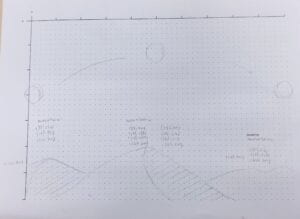
I first drew and simplified the image on graph paper. I used curve and bezier to draw the dunes and its shadow side. But I found it difficult to sketch the shape of cloud, so I added the moon and the sun instead of the cloud to decorate the sky.

Step 3: Draw your image with code & Step 4: Going beyond

I didn’t find the approach to make the color of sky change gradually, so I used several rectangles and filled in blue colors from dark to light. And I animate the positions of sun and moon to let them alternate.

float a=0;
float c=280;
float d=280;
float b=-800;
int mode=1;
void setup() {
size(800, 600);
}
void draw() {
// Your drawing code goes here
background(146,159,191);
fill(131,163,204);//sky
rect(0,0,800,150);
fill(161,178,208);
rect(0,150,800,300);
fill(183,197,223);
rect(0,300,800,450);
fill(174,188,215);
rect(0,450,800,600);
noStroke();
fill(90,75,68,200);//mountain1
beginShape();
vertex(-100,600);
bezierVertex(78,510,167,490,310,600);
endShape();
fill(158,103,73,150);//3
beginShape();
vertex(347,600);
bezierVertex(676,500,760,520,1000,600);
endShape();
fill(158,103,73);//mountain2
beginShape();
vertex(88,600);
bezierVertex(168,588,368,450,664,600);
endShape();
fill(90,75,68);//mountain2'
beginShape();
vertex(347,600);
bezierVertex(388,516,368,510,664,600);
endShape();

fill(#FFFA6A,170);
ellipse(a,c,100,100);
a=a+4;
if(a>=0&&a<=400){
c=c-1;
}
if(a>=400){
c=c+1;
}
if(a==800) {a=-800;c=280;}
b=b+4;
if(b<=400&&b>=0){
d=d-1;
}
if(b>=400){
d=d+1;
}
if(b==800) {b=-800;d=280;}
fill(#FF6040,170);
ellipse(b,d,100,100);
println(mouseX,mouseY);
}

I think drawing in Processing is interesting because it can realize the combination of images and movements. And maybe I can depict a short story with Processing, it is a good means of realizing design.

Categories
Interaction Lab

Midterm Project: Make, Present & Report

A. PROJECT TITLE – YOUR NAME – YOUR INSTRUCTOR’S NAME

Project title: Truth or Dare

Group member: Siwei Chen, Siwen Fang

Instructor: Gottfried Haider

B. CONTEXT AND SIGNIFICANCE 

In the previous group project, we came up with an idea of a camera that can predict the future change of an object or a person based on some algorithm. It interacts with the user because the picture camera prints may change the action of the user, take an example if I foresee a rotten apple in the future, I may tend to put it in the fridge to keep it fresh. To make the artifact more interactive and fun, we decided to design a two-player game. We found the game: Truth or Dare. “Truth or Dare is a mostly party game requiring two or more players. Players are given the choice between answering a question truthfully or performing a dare.”(https://en.wikipedia.org/wiki/Truth_or_dare%3F) The more player joins the game, the more interesting it will be. But as far as I am concerned, the game isn’t so interesting between two players as it might seem like two players answer the question or perform the dare in turns. So we added speed competition and some random elements to our design, which can make the artifact more interesting and interactive. Instead of using button or paddles, we connected the wires to a clapping toy to control the direction of the arrow, which involves “sound” to the game and enlarge the participation of both players. In my understanding, interaction is communication between the object and the user, or between users and users, which can change the actions of both sides by giving input and expressing output. Also, using a combination of senses like the integration of vision and sound can strengthen the interaction of the artifact.

C. CONCEPTION AND DESIGN:

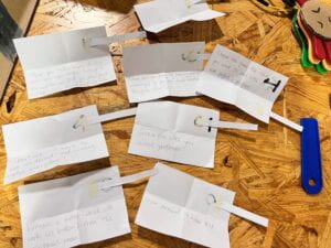
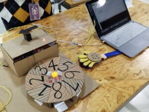
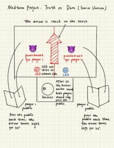
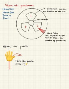
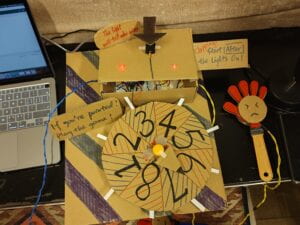
We decided to make a two-player game and add some fun elements like speed competition, sounds, movements, and random, which can enlarge the participation and make the artifact more interactive. And the game we design has a few steps: At first, the buzzer will count down 3 seconds, and in the third second, the LED light will flash means the start of the game. Two players use the clapping toy to control the arrow, the quicker one clap, the more likely he or she will win. Then, after 15 seconds, the game is over and the player who is pointed by the arrow should accept the punishment — Truth or Dare. We prepared Truth or Dare questions and wrote them on the cardboard. The last part of the game is a small fan that spins randomly between 1.5-3 seconds with an arrow stuck on it to decide the question as punishment, which adds more fun to the game playing between two players. To make the game rule clear to players, we wrote it simply beside the artifact. Considering the materials, I first chose the materials that I am familiar with. So we used cardboard and the materials from our Arduino kit. Breadboard, cables, LEDs, buzzers, and resistors are the common materials in building the circuit, and we use a servo to act as an “arrow” that can be controlled. We also added a DC motor with a fan and transistor to choose the question of Truth or Dare as punishment. Actually, in our first draft, we considered using buttons as switches to control the servo, similar to the speed competition game in recitation 2. But after discussing the playability and creativity of the game, we finally selected clapping toys as switches because it is “noisy but more fun”. And we changed the servo from our kit to a standard servo as it is more stable.
D. FABRICATION AND PRODUCTION:

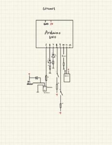
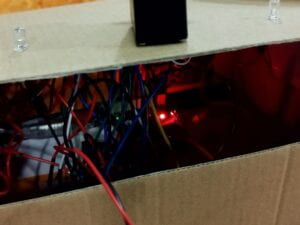
We divided our work: I did the coding and the building of the circuit, and Wendy took charge of the appearance of the work and decoration part. We drew the draft individually and combined our ideas of the artifact, and checked the circuit diagram together to avoid the mistake in advance. I wrote the code first, finding the examples learned in class such as the code for the motor and servo, and tried to integrate them together. However, after rearranging the code many times, because there were many different types of codes, I was still very confused, especially in the servo part, I didn’t know how to let it spin randomly, and had no idea how to make the buzzer count down time. Fortunately, after learning the “millis” code in Tuesday’s class and with the help of the professor, the problem of the code was solved. The building of the circuit went well, except for the motor part. The first attempt to work the circuit went well too, also except for the motor part. I checked the circuit of the motor according to the slide lots of times but could not find the problem. After struggling for nearly several hours, rechecking the motor, changing the Arduino board two times, and rearranging the code again, I found I misconnected the diode: I connected its plus side to the ground and connected its ground to 5V, so the circuit couldn’t work normally. Adapting the connection of the diode, the motor finally worked, however, the servo went wrong. Every time the servo spun, it somehow showed “Not connected. Select a board…” on the serial monitor and restarted the program. With the suggestion from the professor, I added a 5V DC power supply into the circuit and completed the work. 
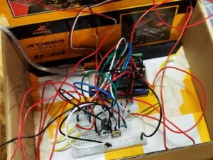
The code:

#include <Servo.h>
Servo servo;
const int pushButton_1 = 8; //player1
const int pushButton_2 = 9; //player2
int a = 90; //angle
int fan = 5; // the PWM pin the fan is attached to
int brightness = 5; // how quick the fan is
int fadeAmount = 5; // how many points to fade the fan by
int num = 1;
int pre_buttonState1 = LOW;
int pre_buttonState2 = LOW;
int flag = 1;
int button; int pre_button=LOW;
int starttime=0;
void setup() {
Serial.begin(9600);
pinMode(5, OUTPUT);
pinMode(6, OUTPUT);
pinMode(7, OUTPUT);
pinMode(fan, OUTPUT);
pinMode(pushButton_1, INPUT);
pinMode(pushButton_2, INPUT);
servo.attach(11);
servo.write(a);
}
int lastBuzzer = 0;
//buzzer
void loop() {
int buttonState1 = digitalRead(pushButton_1);
int buttonState2 = digitalRead(pushButton_2);
// if(millis()==1000){
// digitalWrite(5, HIGH);
// }
if(millis()-starttime == 3000){
digitalWrite(6, HIGH);
digitalWrite(7, HIGH);
}
// this is the most robust solution (we can sleep as long as we want below)
/*
if(millis()>=6000 && millis()<=15000) {
if (millis()-lastBuzzer >= 1000) {
tone(10, 440, 200);
lastBuzzer = millis();
}
}
*/
// here, this increases the window (to a 10th of a second)
if(millis()-starttime == 4000){
 
digitalWrite(6, LOW);
digitalWrite(7, LOW);
}
if(millis()-starttime > 0 && millis()-starttime <= 2000 && ((millis()-starttime) / 10) % 100 == 0){
tone(10, 440, 200);
}
// the window here might be to narrow (if the code below takes too much time)
/*
if(millis()>=6000 && millis()<=15000 && millis()%1000 == 0) {
tone(10, 440 ,200);
}
*/
if(millis()-starttime ==3000 && ((millis()-starttime) / 10) % 100 == 0){
tone(10, 880, 200);
}
//servo
if(millis()-starttime >= 3000 && millis()-starttime <= 17000 && (millis()-starttime)%25==0){
if(buttonState1 == HIGH && buttonState1 != pre_buttonState1 && a >= 0){
//Serial.println("button 1");
a = a - random(-1, 10);
//random(-1, 10);
}
if(buttonState2 == HIGH && buttonState2 != pre_buttonState2 && a <= 180){
// Serial.println("button 2");
a = a + random(-1, 10);
//random(-1, 10);
}
pre_buttonState1 = buttonState1;
pre_buttonState2 = buttonState2;
Serial.println(a);
/*
a = a + -2 + random(5);
if (a < 5) {
a = 5;
}
if (a > 175) {
a = 175;
}
*/
if((millis()-starttime) % 100 == 0){
servo.write(a);
// Serial.println(a);
}
}
//LED
if(millis()-starttime == 17000){
if(a < 90){
digitalWrite(6, HIGH);
}
if(a > 90){
digitalWrite(7, HIGH);
}
Serial.println("F");
}
//delay(5);
 
//fan
if(millis()-starttime > 17000 && flag==1){
digitalWrite(5, HIGH);
delay(random(1500,3000));
digitalWrite(5, LOW);
flag=0;
}
}

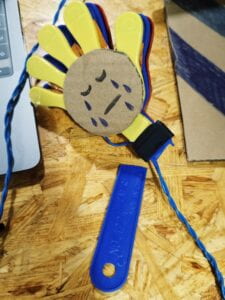
In the user testing session, our artifact broke: the soldering part which connected the wire and the clapping toy broke and fell. And we also received some feedback that we should make the rule clearer, and we should use the same color of cables and LEDs as the color of clapping toys to make it easier for players to understand the rule. So I changed the code of the buzzer to make it count down 3 seconds before the game started, and Wendy wrote the rule on cardboard, sticking it on the artifact to make the rule readable and clearer to the player. We remade the connection between the clapping toys and the circuit, using suitable wires and decorations. The adaptations made our artifact more playable.
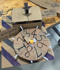
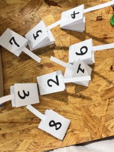
       

E. CONCLUSIONS:

Our goal for the project is to design an interactive fun game. The game we design involves two players, it forms a communication based on the game between one user and another user. With the sound of clapping and the movements of players, our project aligns with my definition of interaction. Hoping that the players can enjoy themselves and have fun in the game. If we have more time, I think we can improve the appearance of the artifact to make it look better, maybe more buzzers and LEDs can be used to polish the playing method. From the painful process of building and checking the circuit of the motor, I learned to be more careful and patient. I know more coding knowledge from this accomplishment and have a basic understanding between the circuit and the code. From the beginning of the idea of the design to the final finished artifact, Wendy and I collaborated, we solved problems step by step and ensured all parts of the artifact centered on “interactive”, which refreshed and deepened our understanding of interaction.
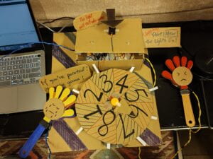
By the way, the clapping toy broke at the end 🙁
Categories
Interaction Lab

Recitation 4

Step 1: Build the circuit

I followed the circuit picture given and built the circuit. Luckily, the wiring was correct, and we programmed Arduino with the example code. We found the motor rotated smoothly and made one revolution.

Step 2: Build a cardboard mechanism!

In step 2 we need to build the cover of the machine with cardboards. We spent most of the time cutting the cardboard and glueing it together. Then, we connected the DC motor to the artifact. Finally, with our joint effort, we made it, and we drew a cube and stuck it to the motorized arm.

Step 3: Personalize it

Finally, we tried to change the rotation speed, degree and the delay to make it spin faster. This is the step where we met with difficulties. We found that every time we tried to increase the value in the code, the motor would stop spinning and only make noise. Then we asked the instructor, and surprisedly found that we should connect a wire with a larger voltage in order to run the motor. We eventually made the motor spin faster.


Additional Questions

Question 1: Choose an art installation mentioned in the reading ART + Science NOW, Stephen Wilson (Kinetics chapter). Post your thoughts about it and make a comparison with the work you did during this recitation. How do you think that the artist selected those specific actuators for his project?

The art installation: Ken Rinaldo and Matt Howard, Autotelematic Spider Bots, 2006

This art installation integrates the features of ants and spiders. It can interact with visitors and communicate with electrical recharge ports to learn from artificial-life behaviors. I think the art installation may use some rotating mechanism in its movements. In our recitation class, the artifacts we made uses the motor to spin and rotate, which may similar in the art installation. Converting energy into lots of motion, this art installation is really amazing!

Question 2: What kind of mechanism would you be interested in building for your midterm project? Explain your idea using a sketch (conceptual or technical) with a list of materials that you plan to use. Include details about the ways that you expect the user to embrace in a physical interaction with your project. In particular, explain how would your motor (or motors) with a mechanism will be different than using an animation on a digital screen.

In my midterm project, we plan to use servo and DC motor to add the rotating mechanism. The material we will use: laptop, servo, LEDs, cables, DC motor, buzzer, cardboard, mini fan, resistors, transistor, breadboard, Arduino set. We use the clapping toy instead of the switch to control the direction of the arrow. When the game begins, the LED lights up, the buzzer makes a sound as a signal, and players on both sides compete speed with the clapping toy. When game is over (after 15 seconds), the player who is pointed by the arrow should accept the punishment — Truth or Dare. We plan to stick Truth or Dare questions on the small fan to decide the question as punishment. We try to add more fun elements to this game by adding a speed contest and using random to compete for luck, which adds more fun to this game between two players. 

Categories
Interaction Lab

Midterm project proposal

Title: Truth or Dare

Group members: Siwei Chen, Siwen Fang (Wendy)

Instructor: Gottfried Haider

Topic: Game design (To play, for fun)

Reference: https://en.wikipedia.org/wiki/Truth_or_dare%3F

We use the clapping toy instead of the switch to control the direction of the arrow. When game is over, the player who is pointed by the arrow should accept the punishment — Truth or Dare. We plan to stick Truth or Dare questions on the small fan to decide the question as punishment, which adds more fun to the game playing between two players. 

Categories
Interaction Lab

Group Research Project: Make, Perform & Report

REPORT:

We got our idea from the story: The Veldt– Ray Bradbury

“George Hadley walked through the singing glade and picked up something that lay in the comer near where the lions had been. He walked slowly back to his wife. “What is that?” she asked. “An old wallet of mine,” he said. He showed it to her. The smell of hot grass was on it and the smell of a lion. There were drops of saliva on it, it bad been chewed, and there were blood smears on both sides.” (Ray Bradbury, THE VELDT )

In this part of the story, George, the father, found a dirty wallet covered with saliva and blood, which implied the fate of the couple.

Searching the technology that exists, we find two types of technology. One is the AR technology that helps us see what the cultural relics look like thousands of years ago. The other one is the AI technology that helps us see how we look when we are old.

After reading this, we came up with an idea: How about making a camera that can predict what will happen in the future? Isn’t that cool?

But we foresaw some problems of the camera, if everyone can use the camera to see the future, will he or she accept the destiny or try to change it? Is everyone willing to see what life he or she lives in the future?

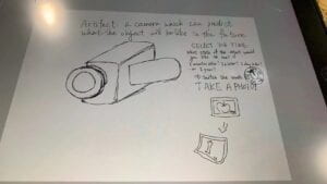
Decided the function and the model of the camera, we had our first sketch.

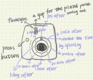
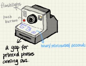
Angel drew two sketches of the camera with details, we chose the latter one.


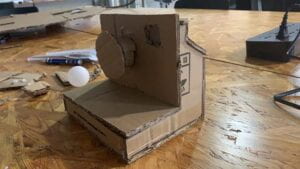
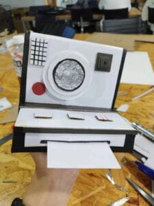
Like common cameras, our camera has flashlight, push button on it. Combined with the characteristics of the Polaroid, the camera can print photos in time after taking photo every time. The unusual point is that the camera can predict what will happen in the future, with three buttons to adjust the predicted time, choosing to predict a year, a day, or an hour, or a minute later. The camera uses some sophisticated algorithm and artificial intelligence to achieve the prediction.

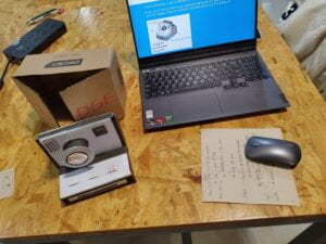
Amelia and Almon made the model of the camera with cardboard.

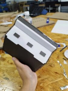
I did the decorations. I reinforced the structure of the camera with the scrap of colorful cardboards, and the use of black and white makes the camera look simple yet futuristic. I cut the cardboards into small pieces and stuck it a row onto the camera as buttons. To make the camera look better and more realistic, I used silver paper and stuck it in front of the camera lens. Also, I found a black tape in my tool bag, it’s very useful. It has a good stretchability and can be used to fill some small gaps. After two hours working, the decoration step finished! 

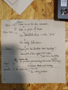
Rebecca wrote the script of our performance and made power point to illustrate the general process.

Our script:


We played our different roles in the performance. Almon found the camera by chance and showed the strange camera to us. We wanted to figure out the function of the camera, so we decided to take a picture. Almon tried taking a picture of me, and the camera printed a photo of me falling down. And then, after some seconds, I really fell down. Above that, we speculated that the camera could predict the future.

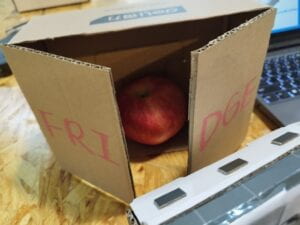
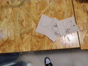
To show the interactive way of the camera, we took the picture of an apple and got an output of a photo of rotten apple after one day. To avoid this happening, we put the apple into the fridge and got a photo of the fresh apple. In the process, the camera interacted with us, the output of it changed our actions.

The fridge and photos prepared:

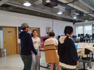
Discussion & Rehearsal:


Watching other group performance, I’m interested in the automatic machine performed by group 4. The idea of the artifact was inspired by The Plague , written by Yan Leisheng, which tells the story of a civilization that was wiped out by a kind of virus. This automatic cleaning machine can eliminate the virus in human body with ultraviolet rays, and has the function of washing and drying, which can effectively sterilize. The performance is humorous and easy to understand. The function of the machine is directly expressed from the “patient”, which deepened our impression of the performance and broadened our understanding to the artifact. But there still remains shortage, as I haven’t found interactive points in this artifact. It’s like a reactive machine, not interactive machine. If the output of the machine can change the actions of people, for example, the machine can analyze the result of the examination of body and give suggestions to patients, which affects patients behaviors in the future, the artifact will be interactive and better.

The performance of automatic cleaning machine:

This group research project was very interesting. My team members and I collaborated to design and build our works, rehearsed and performed together. We have further discussed and understood the meaning of interactive, and also found new creative ideas from the performances of other groups. I’m looking forward to the next group project!


Categories
Interaction Lab

Recitation 03

Step 1: Prepare your tilt sensor

Task #1: We need to connect the wires with the sensor. At first we followed the picture given and just twined the iron wires together, but we found they could not connect tightly. So we used tape to fix the wires and soldered the sensor to two long wires carefully.

Task #2: To connect the tile sensor cables to the Arduino, we followed the circuit. One side of the tilt was connected to GND, another side was connected to a resistor, which linked to the 5V.

Task #3: I programmed the Arduino with the sketch, it worked correctly. When monitoring the tilt, I found that every time I shook the tilt, it would send the information  “0” or “1”. 


Step 2: Refine the code

​​To let the program only print 1 when the tilt sensor changes from 0 to 1, and 0 when from 1 to 0. I uploaded the sketch, added

if (tiltVal != prevTiltVal) {
    Serial.println(tiltVal);
    prevTiltVal = tiltVal;

As a result, I got a chain of “0” and “1” in the monitor page.


Step 3: Wear your sensor

We stuck the tilts with tape to our arms, and held the tape as hand weights. By moving our arms, the tilts can sense the movement and send the information constantly.


Step 4: Bicep Curl Workout!

The coding of Step 4 is as followings:

int SENSOR_PIN = 2;
int tiltVal;
int prevTiltVal;
int num=0;
int a=0;
void setup() {
  Serial.begin(9600);
}
void loop() {
  // read the state of the sensor
  tiltVal = digitalRead(SENSOR_PIN);
  // if the tilt sensor value changed, print the new value
  if (tiltVal != prevTiltVal) {
    if(tiltVal==HIGH){
      num=num+1;
      a=a+1;
    Serial.println(num);
    }
    if(a==8){
      a=0;
      Serial.println("Yay, you’ve done one set of curls");
      delay(100);
    }
    prevTiltVal = tiltVal;
  }
  delay(10);
}
Step 5:Exercise Challenge
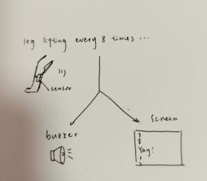
My partner wore the sensor on his leg, and every time he kicked, the serial monitor added a number to the output. And after every 8 kicks, the buzzer that was newly added by us would make a sound and the serial screen would print “Yay, you’ve done one set of curls”. 

The coding of Step 5 is like:

int SENSOR_PIN = 2;
int tiltVal;
int prevTiltVal;
int num=0;
int a=0;
void setup() {
  pinMode(8, INPUT); // Set sensor pin as an INPUT pin
  Serial.begin(9600);
}
void loop() {
  // read the state of the sensor
  tiltVal = digitalRead(SENSOR_PIN);
  // if the tilt sensor value changed, print the new value
  if (tiltVal != prevTiltVal) {
    if(tiltVal==HIGH){
      num=num+1;
      a=a+1;
    Serial.println(num);
    }
    if(a==8){
      a=0;
      Serial.println("Yay, you’ve done one set of curls");
      tone(8,440,1000);
      delay(100);
    }
    prevTiltVal = tiltVal;
  }
  delay(10);
}


My own illustration sketches:


Experience and Learning:

Actually, I didn’t notice at what angle the tilt will transition between HIGH and LOW, but I think if I lean it to the right, the tilt will transition to HIGH or LOW, and then I lean it to the other side, it will transition to the opposite information. If I shake the tilt, it will send a constant piece of information like: 0101010101010101
 If I hold the wires several centimeters away and tilt, it still work. I think this device can be used by any user, it is interactive because it includes listening and thinking, and the output of the information “Yay, you’ve done one set of curls” also influence the thought of the user so that the user can decide whether continue doing another set of curl or stop exercising.

Categories
Interaction Lab

Recitation 2

Circuit 1: Fade

The first step is to let the LED fade automatically and light up again through the Arduino Uno, and then repeat the cycle. I followed the circuit diagram to build the circuit, and found the sample in the software, successfully completed.


Circuit 2: toneMelody

In the second step, I need to add the buzzer to the circuit and let it make a piece of melody. After matching the circuit with the diagram, I opened the file to operate the code, and the buzzer sent out a short piece of melody “↑↓↓↑↓↓↑”.


Circuit 3: Speed Game

In the third step, we need to match the circuit. When I first saw such a complex circuit diagram, I was afraid of making mistakes because it would take a long time to check the circuit. We followed the circuit diagram step by step carefully. After completing the building, I ran the code and tried pressing one side of the button many times. Then  the LED turned on. I tried again on the other side, and the circuit worked smoothly. Succeed!


Optional 1. Switch out the pushbuttons with the DIY paddles you soldered during the previous recitation.

We used the switch made by our own in the last class, and replaced the push-button switch. Having a match with the board-made-switches was more interactive and more interesting!


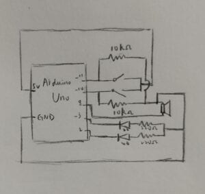
My own drawing of the schematic for circuit 3


Question 1: Propose another kind of creative button you could use in Circuit 3 to make the game more interactive. Read and use some material from the Physical Computing, Introduction Chapter (p. xvii – p. xxix) to explain why this button would make this game more interactive.

I think it will be cool if the button in circuit 3 can be a sound sensor. When a person claps his/her hands a time, the sound will be received by the sensor as an input and transform into a score. If either of the person reaches 10 scores, the light of his/her side will turn on as an output which means victory. The input part is not simple as clicking the button, it involves clapping, including both listening and thinking. Then it will transform the sound into electrical information in the processing part. The  computer calculates and calculates the number of clapping from both sides. based on the changes it reads, when the number adds up to 10, the computer activates output—turn on the LED. The whole process includes listening, thinking and transduction, which makes it more interactive.


Question 2: Why did we use a 10 kOhm resistor with each push button? 

The resistance of 10 kΩ is connected in the circuit, so that the circuit is in the connected state, but because the resistance is too large, the current becomes so small that the LED cannot glow. When the switch is closed, the current passes through the branch of switches with a small resistance value, the current becomes larger, and the LED shines up.


Question 3: In the book Getting Started with Arduino there is a clear description about the “Arduino Way” in chapter 2. Find a project that you find interesting that can be used as an example for these kind of projects. Cite it in adequate manner, include a picture, and explain the reasons that you chose it.

In the article, the author describes Arduino:“The Arduino philosophy is based on making designs rather than talking about them. It is a constant search for faster and more powerful ways to build better prototypes. We have explored many prototyping techniques and developed ways of thinking with our hands.”(5)

I found a project named Everything & More & More on the creative applications website that can be used as an example for the description. 

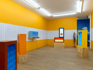
“In MORE&MORE: “China, India, Japan, Mexico, Turkey, USA” (2016), six video sculptures of various shapes and colours are situated throughout the space, some placed upon wooden boxes that evoke shipping crates. The algorithmically generated visuals portray a looping combination of shipping motifs and abstract mosaics: cranes load and unload cargo, ships cross bodies of water and trucks transport to and from ports day and night in all manners of good and bad weather. In one video, oil droplets stretch down the screen.”(Marina Zurkow and Rachel Rose. (2016, March 14). 

Everything & More & More – Marina Zurkow and Rachel Rose. Creative Applications.

https://www.creativeapplications.net/events/everything-more-more-marina-zurkow-and-rachel-rose/ )

Like what the author said in the article, the project used simple things—wooden boxes that evoke shipping crates, 3D powder, plaster
combined with interactive design to express the idea of the show. The old stuff was tinkered, reduced, patched to make them do something new, to endow them with new meanings. They might be junk before, but after scratching and redesigning, they were exhibits with new ideas, which was in the description of the “Arduino Way”.

Categories
Interaction Lab

Group Research Project Step 1 Read

1.The Veldt

This story tells of a high-tech era, where children gradually regard machine technology as their parents, and abandon their real parents.

In the story, there is a mind-reading room in the nursery, which can show the scene exactly as you imagine it. It can control the temperature, humidity, smell and make people feel right there. 

So I came up with the idea of “ Portal” . Place such machines (perhaps a room) around the world: they are able to record and transmit the local environment, temperature, humidity, oxygen levels, etc in real time. If I go in and choose where I want to go, the whole room can simulate the environment and adjust to where I want to go, maybe Africa, the Antarctic, maybe deep under the sea, mountains… As long as a place has the same machine, you can choose to “go” to those places, have a different experience, and complete a virtual tour.

I think the existing technology can accomplish this kind of design. For example, in order to train astronauts, we specially designed the simulation of the space environment, and some advanced VR equipment can already simulate the temperature and smell.

But I think there are some problems with this technology, too realistic simulation of the environment can be harmful. First of all, some people may not adapt to certain environments, such as overheating or too cold, which will cause problems if directly simulated. Secondly, virtual products may give people a kind of illusion, as expressed in the article, it is easy to make people confused between the real and the fake, resulting in a series of problems.


2.The Ones Who Walk Away From Omelas

The story exhibits a world “Omelas” , where there was no grief and sadness, but at the cost of losing a child’s happiness forever.

There’s no details about how to exchange people’s sadness and happiness in the article. But maybe we can find a method to analyze a person’s feelings and emotions, then provide a physical or mental way to solve some related problems. 

I imagine a piece of software, when it looks at a person’s facial expressions, words and movements through a camera, it can accurately analyse his or her emotions to provide advice accordingly. For example, when the system senses a person’s sad emotion, it questions him to understand the cause of sadness, and makes use of big data analysis to give reasonable suggestions, which can effectively relieve his or her sad emotion.

Recently, facial recognition has been used more and more widely, whether to unlock your phone, authenticate your identity, or even replace manual payments in some applications. There is also a lot of research on facial expression analysis, and I found a project on the website that matches the first part of my idea: ă€Šæƒ…ç»ȘÂ·ć…ƒç”ă€‹(Yoooooon. (2022, September 22). ă€Šæƒ…ç»ȘÂ·ć…ƒç”ă€‹. MANA.

https://m.manamana.net/video/detail/2003565#!zh)

This work of art uses an artificial intelligence program to read the emotional data in the facial micro-expression, and translates the audience’s current thoughts and emotional states into the emotional element spirit in the virtual world in real time. It analyzes people’s emotions by recognizing their facial expressions.

But there are some drawbacks of my idea. Can a machine really fully understand human emotions based on big data alone? If the analysis goes wrong, the advice given can backfire.


3.THE PLAGUE

The story pictured an era when human beings are attacked and petrified by a kind of virus. In the story, petrified people become another form of life, still conscious, but only moving at a very slow speed.

Is there a way to “resurrect” what we call “substance”? Such as some ancient relics, some underground ore. If we had a technology that could analyze the traces of a substance to infer its experience, to tell its story, then we could learn about a new different form of life. With such interactive artifacts, we could even tell the story of a rock found by a river.

Now we can observe ancient relics, by analyzing the different matter covered on it, to speculate its age, its use. I also found a way of telling the story of the ancient relics on the Internet: Arche-Scriptures – Our digital traces in the future-past.

“Created by Alberto Harres at HfK Bremen, ‘Arche-Scriptures‘ explores ceramics as a possible medium to store digital information. An artifact found at a speculative archeological dig-site is being scanned by a decrypting machine, through which the visitor is invited to listen as the original audio data engraved onto the ceramics is slowly retrieved and sonified. The experience offers a glimpse on a possible future past, it speculates on the future of our digital traces through an ancestro-futuristic perspective, provoking a discussion about continuity, preservation and archiving.” (Harres, A.& Bremen,H. (2022, January 8). Arche-Scriptures – Our digital traces in the future-past.Creativeapplications.

https://www.creativeapplications.net/processing/arche-scriptures-our-digital-traces-in-the-future-past/)

The project used technology to translate the past story to an original audio. It will be more amazing if one day a more advanced technology enables us to know the story of all the things around us.