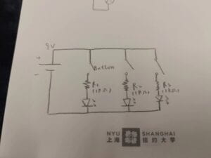
Task1 step1:The circuit is made up of a power, a buzzer and a button. The battery provides electricity to the buzzer.The button can control the whole circuit: press the button and the circuit can work, the buzzer makes a sound; if you don’t press the button, the circuit is disconnected and it can’t work.
We built the circuit according to the picture given. The first time we connected the circuit, we pressed the button but didn’t hear the sound from the buzzer. We moved and tested the components one by one and found the button was misconnected. The button has four legs and the two opposite legs should be connected into the circuit so that it can turn on/ off the circuit. After we had put the button in the right position and connected it, the circuit worked.
Task1 step2: there’s a new branch of the circuit in the picture. A resistor and a LED are connected parallel to the buzzer. The button can control two circuit branches at the same time.
We added a new branch beside the circuit we built before. It began with the positive side of the battery and ended with the button. Luckily we didn’t make any mistakes this time and the circuit worked smoothly.
Task1 step3 : there’re three branches in the circuit in all. The third branch has a POT, a resistor and a LED. The POT acts as a controller to the LED. When turning the POT, the whole resistance of the branch changes, so the currency of the branch changes too. As a result, the light of the LED becomes brighter or darker.
At first, we had no idea how and where to put the POT. Sliding down the webpage, we found a reference about POT: the left leg connects to LED, and the middle leg connects to the resistor. Then we connected the LED1 to the button by mistake, the LED1 was wrongly controlled by the button. After correcting the connection, the LED1 was always lit and could be controlled by the POT successfully.
The task looked difficult at first because most of the things were new to us like the breadboard, buzzer, potentiometer, but after we carefully observed the circuit, repeatedly tried, and collaborated with each other, we completed our task finally.
Task2 : we are brought to soldering stations to use cardboard, copper tape, and wires to build a switch. We learnt that metal can conduct electricity, and the way to bond metal together—soldering. I think this task is easier than task1. We cut the outside of the wire and soldered the inner electric wire to the sheet metal stuck on the cardboard. We stuck the cardboard with copper tape and built a switch. The metal part of the switch can be controlled by our hand. When we close the two parts of metal sheet together, the switch is connected; when the two parts are separated, the switch is disconnected.
Task3: we switched the switches and tried making Morse code. Very coollllllllll
Question1: LEDs need resistors to help limit the current so they do not get damaged. The current should not exceed the LED’s limitation and resistors can limit the current for the LED.
Question2:

Question3: I think task1 and task3 include interactivity. In task1, we can control the buzzer by pressing the button, just like kids opening the fridge in the article. In task3, we control the buzzer by the switch we made to make Morse code. To the circuit, the interactivity between it and me is low. When I press the button and it makes a sound, the interactivities are mostly in one way. To the group, between my group mate and me, the interactivity is high, because we made Morse code to send information to each other. In the process, we listened, thought, acted and spoke by sending Morse code, it’s interactive.
Question 4: physical computing can be the process and approach to the works, interaction design is the idea and origin of the works. In the video, Zack had the interaction design of the car and used some softwares and physical computing to make the car drive in alphabet. The design and physical computing together create interactive art.