Categories
interaction lab recitations

Processing Basics

step1: 

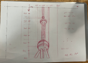
I chose this photo as a reference:

step 2: image on paper:

step 3: 

As could be seen in the picture, I took me way to much time to figure out the numbers and position of the objects that by the end of the recitation I didn’t have that much done. But I had added some details at home. 

if i had an opportunity to spend a bit more time on this, i would’ve added a bit more shadows/volume to this.

In the code, i used vertex(), strokes() and ellipse() to create this. It was pretty effective to divide the Pearl in these shapes.

the code: 

int i = 0;

void setup(){
  size(400, 700);
  background(40, 120, 212);
}

void draw(){
  fill(141, 145, 150);
  noStroke();
   ellipse(200, 125, 30, 30);
   stroke(50, 64, 80);
   strokeWeight(20);
   line(200, 130, 200, 150);
    fill(141, 145, 150);
    noStroke();
  ellipse(200, 200, 100, 100);
  strokeWeight(20);
  stroke(141, 145, 150);
  line(185, 220, 185, 460);
  line(215, 230, 215, 460); 
  noStroke();
  ellipse(200, 540, 160, 160); 
  strokeWeight(30);
  stroke(141, 145, 150);
  line(160, 600, 90, 700);
  line(180, 580, 180, 700);
  stroke(50, 64, 80);
  line(240, 600, 240, 700);
  stroke(141, 145, 150);
  line(210, 560, 260, 700);
  stroke(0);
  strokeWeight(10);
  beginShape();
  vertex(120, 550);
  stroke(141,113, 140);
  strokeWeight(40);
  quadraticVertex(200, 480, 280, 550);
  endShape();
  //upper curve
  beginShape();
  vertex(150, 210);
  stroke(141,113, 140);
  strokeWeight(30);
  quadraticVertex(200, 150, 250, 210);
  endShape();
}

Categories
interaction lab recitations

Actuators & Mechanisms

In the beginning of this recitation me and my partner (Dana) briefly went through the tasks and then divided responsibilities: I was in charge of the cardboard work, while Dana was following the instructions and connecting the wires. 

  • Cardboard struggles (none)

As I spent past two weeks with a glue gun in hand for another class, the gluing and folding part were quite easy for me. I found the paper cutouts a very useful and great idea! It took me approximately 20 minutes to assemble. 

  • Wiring struggles 

Dana has followed the instructions precisely, and got that as she forgot to connect it to the higher power:

After I reminded her of that, we were basically done with the base. 

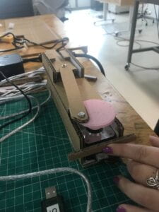
Then, when we put the motor into the construction, we realized that due to the movement it kept falling out, so we added this cardboard “fence” to prevent that:

and moved forward to personalizing the construction.

  • personalization: idea

from the very moment we have assembled the construction we had an idea of making it look like a frog that moves her tongue to catch a fly (doing that at the same speed but random intervals). so we decided to make the tongue look like an actual tongue by painting it read in some places + adding two eyes and add some green details as well. 

  • code

as for the code, i have already mentioned the random() delay idea. we also personalized the steps per revolution. //you can find the code in the end of the post//

the final result:

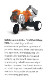
Question 1: Choose an art installation mentioned in the reading ART + Science NOW, Stephen Wilson (Kinetics chapter). Post your thoughts about it and make a comparison with the work you did during this recitation. How do you think that the artist selected those specific actuators for his project.This is the project I have chosen called Feral Robot Dogs by Natalie Jeremijenko. This use of actuators is similar to what we did they are used to mimic animal part’s movement. Our was the tongue, here is the movement of a dog. Also this project is quite interesting as it has an element of environmental activism to it, which is always great! I am curious how the sensors work though, do they somehow detect the clarity of the air? fascinating. 

Question 2: What kind of mechanism would you be interested in building for your midterm project? Explain your idea using a sketch (conceptual or technical) with a list of materials that you plan to use. Include details about the ways that you expect the user to embrace in a physical interaction with your project. In particular, explain how would your motor (or motors) with a mechanism will be different than using an animation on a digital screen.

this is my midterm proposal:

midterm project: proposal

The mechanism that I am planning to build for the midterm does not really involve motors. We might use it to display how our puzzle work. Me and my partner are going to experiment with how we can make the interaction a bit more interesting and complex (from technical side). 

*
 This program drives a unipolar or bipolar stepper motor.
 The motor is attached to digital pins 8 - 11 of the Arduino.

 The motor should revolve one revolution in one direction, then
 one revolution in the other direction.


 Created 11 Mar. 2007
 Modified 30 Nov. 2009
 by Tom Igoe

 */

#include <Stepper.h>

const int spr = 400;  // change this to fit the number of steps per revolution
// for your motor

// initialize the stepper library on pins 8 through 11:
Stepper myStepper(spr, 8, 9, 10, 11);

void setup() {
  // set the speed at 60 rpm:
  myStepper.setSpeed(56);
  // initialize the serial port:
  Serial.begin(9600);
}

void loop() {
  // step one revolution  in one direction:
  Serial.println("clockwise");
  myStepper.step(spr);
  delay(random(200-400));
/*
  // step one revolution in the other direction:
  Serial.println("counterclockwise");
  myStepper.step(-stepsPerRevolution);
  delay(500);
  */
}
Categories
interaction lab recitations

Workout

STEP #1: all of the tasks && STEP #2

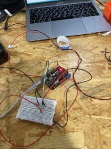
Soldering is something I have done on the first recitation, however that time I had Lydia to assist me almost all the way through. This time, on the other hand, I had my friend by my side, however I really wanted to do it myself first. In retrospective, probably spent way too much time on that, next time going to ask for help sooner. The problem I had was that the silver wire was melting but i couldn’t attach it to the wires (it kept sticking to the soldering machine instead of leaving to connect two wires). I then asked my friend how she was handling that and she showed me those king of circling movements that she was doing to stick the melted pieces of wire when they are supposed to go. Anyways, after 30 min or more, I managed to solder the wires, put the circuit together and even start programming. However, my computer decided to give up on me again, so when my friend was busy with something else, I create a file on her computer, refined the given code and tried out my circuit.

and it worked! (u can see my computer going crazy there in the beginning). So, so far the only issue I had was the soldering and my lazy computer. 

STEP #3

my friend helped my film those videos as we wore the sensor to test the code. 

STEP #4 && #5

As my computer was not exactly working with my Arduino, I used my friend computer to complete the last steps. 

  1. We increased the delay to 1000 to count only LOW to HIGH changes
  2. We added the conditionals and installed the buzzer to the 6th pin: 

if  (count == 8) {

Serial.println(“Yay, you made it!”);

tone(6, 440);

count = 0;

}

3. We didn’t have that much time left so we just recorded the video and disassembled everything. 

Anyway, I believe that given the limited time that we had – we did a great job! Special thanks to my friend who let me use her computer.

I probably need to do something about my computer. Not sure what yet. 

Categories
interaction lab recitations

Arduino Basics

circuit 1: Fade

when assembling this circuit, I didn’t encounter any issues as we have already done the same one on the lesson on the previous day. I used significantly less wires this time!! good start.

circuit 2: toneMelody

Unlike the previous circuit, I had a problem with this one. My computer decided to give up on me and would not do anything when uploading the code to Arduino. I reassembled the circuit a couple of times, changed my buzzer and then, when nothing changed, I decided to try and connect my circuit to my friend’s computer. And it worked (that is what is I showed in the video). That is how I made sure that the problem was my computer. The circuit was fine from the very beginning. For the next two circuits I was simultaneously trying to restart my computer and the Arduino Program, while assembling the next circuits and trying them out on my friend’s computer.

circuit 3: Speed Game

This one took me a bit longer. As I was also wasting my time on restarting my computer, and given how saturated with wires the circuit is, it was easy to lose a strain of thought. I also had some struggles with figuring out the direction of the flow, (in the video below you can see how the LED is not lighting up).

but I fixed the issue quickly and this time everything worked:

___________________________________________________________

q1: Instead of button we could’ve created a button that would react to the sound of the hand-clapping. This would make the game much more interactive as it wouldn’t be j

q2: the reason why we used a 10 kOhm resistor with each push button is that when the button is not pressed, without the resistor, the voltage that reaches the Arduino pin is not GND, but it should be. Resistor helps with that. 

q3: Detect Someone Taking Your Stuff and send Gmail

https://create.arduino.cc/projecthub/iot_lover/arduino-detect-someone-taking-your-stuff-and-send-gmail-84c1c4?ref=tag&ref_id=home%20automation&offset=24  

The coolest thing about this project is the GMAIL sending thing. I really want to learn how to do that.

Categories
interaction lab recitations

electronics & soldering

due to my absence on the actual recitation that took place on friday 16th, i attended a meeting with Lydia, interaction lab learning assistant so that i can catch up with the work! 

as i have only attended interaction lab once (this week) i only saw LED, wires, breadboard and resistor in action. i have also went through the multimeter with professor Gottfried and probably much more, however didn’t remember much straightaway. so, when it came to picking up the needed materials, i sought help from Lydia:) e.g. when i saw a variable resistor i didn’t even know how to connect it and what should i do with it. i diverge. as needed, i started with the task 1.

task 1: step 1

built it almost from the first try. Lydia helped me to understand how am i supposed to connect the button to the circuit (turns out if i connect two non-diagonal parts with a wire it doesn’t work, wow).  so, after a small struggle i was able to complete the task.
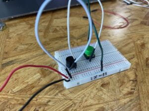
*in retrospective, i probably could have used a bit less wires for it too look more decent, but at the time i didn’t know that i am going to build on on this structure. 

task 1: step 2

task 2 started with the realization that it is basically a build-up for the task 1. sadly, this realization came after i already deconstructed the task 1 circuit. so i had to reassemble it again (took me a minute) and then started to do the task 2. shortly, i completed the task. the only problem i encountered was that i forgot that the LED’s long leg is supposed to go from the “+” charge, which i din’t notice i put in the “-“. Lydia reminded me of that and i got it fixed pretty quickly. so, my circuit worked perfectly again.

again, probably could’ve used less wires. however my decision to move the LED on the other side worked out perfectly as in further steps it became easier to connect the variable resistor. here, i also consulted with Lydia regarding reading a circuit scheme and she helped me to understand the algorithm of building one (usually start from the outer lap and then step-by-step build the inner laps). 

task 1: step 3

the third step was quite easy, except for figuring out the variable resistor as it took me some googling to find out how to connect it properly (that one leg should be connected to the +, another to the – and the middle one to the object (LED in this case)).

only after assembling it i realized what the variable resister actually was doing (varying the potential charge going through the LED). it didn’t stop me from building it though, so i believe it is fine. also, less wires next time (going to try).

task 2

as for the second task, Lydia showed me what i was supposed to make and walked me through the steps. doing the soldering was probably the hardest part, however as i had some previous

knowledge and some skill (two years ago i tried soldering at school) it didn’t take me too much time to figure out what to do. and then i connected the wires to the breadboard and finished the circuit! I personally really liked this DIY part as it made the whole work a tiny bit more personal and handy! 

I didn’t really had a partner to complete the morse code thing, but i hope it is fine! the fun part wasn’t that important to the circuit anyway! 

additional questions

  • Question 1: What is the function of the resistor R1? (You can read about the reason why LEDs need resistors here)  

The function of the resistor is to limit the amount of current (that comes from the power source) to a value that is in the range of LED’s forward current ratings (not higher for sure). Because usually the range of the LED’s forward current is lower than 5V and we usually use 5V power source. If we don’t use resistors the LED will burn out. 

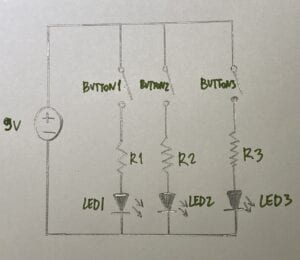
  • Question 2:  Looking at the following circuit, draw its diagram by yourself. 

*not sure about the labels
  • Question 3: After reading The Art of Interactive Design, in what way do you think that the circuit you built today includes interactivity? Which degree of interactivity does it possess? Please explain your answer.

I believe that the circuit that we build today includes three main ways of how we receive information: we can listen to the buzzer (if its on – it means the circuit is active), then we can touch it (as it reacts to when the button is pressed + when we use variable resistor to dim or brighten the second LED), and we can also see the change in the LED’s behavior when the button is pressed. we can’t really speak to it, however we can use it to speak Morse code, which should definitely count for something! overall, i believe this pretty much prosaic system is quite interactive, while having quite a limited number of its state variations (buzz on/of (long/short), light on/of, dimmed light/bright light).

  • Question 4: How can Interaction Design and Physical Computing be used to create Interactive Art? You can reference Zack Lieberman’s video or any other artists that you know.

I believe that using Physical computing (a bit more advanced ones though than we used today, such as scanners or trackers of movement, eyesight, voice, face expressions) there are numerous ways of creating something quite extraordinary as any human will be attracted to something that reacts to it (especially if it is some engaging, intriguing way). For example the clothing that was reacting to the direction of the person’s view. i believe that it is such an interactive and novel idea!