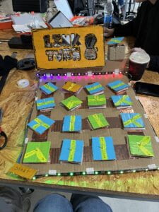
Our project was inspired by a minimalistic game “Linko” as it is mentioned in the proposal. We did not end up creating a kids-friendly game, however we have, in my opinion, succeeded in creating a fun interactive iteration of a linking game. Our goal was to make people want to engage with the pieces and feel rewarded when solving the puzzle, which we were striving to achieve by incorporating bright colors, the song and rainbow LEDs.
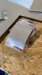
In the first week of making, we had a lot of problems with actually finding out ways how to connect the pieces (they should form a circuit when turned at a certain way). Cardboard pieces were too light to be pressing themselves onto the copper tape. So we sought help from Andy and he proposed this idea of attaching the plastic in a certain way and then fixating the position of a piece for it to apply pressure on the plastic, so that the copper tape is pressed onto another copper tape. So, as we spent a very long time figuring out the mechanics of that, our code and the game overall was not as finished as we wanted it to be. Regardless, we hoped that it would be just enough for the first User Testing, as it might give us an idea/inspiration regarding how we should approach future enhancements of our prototype. So, during the User Testing we have received tons of valuable feedback such as:
so, we did all of that. we added the LED strip, we added the sound and we added bright and fun colors. (code and photos could be seen in the end of the post).
As for this process of enhancement, we were meeting pretty much everyday with Isa to do the work and we were finishing up the thing on Tuesday. As I was in charge of the code, I can share something that I was making the mistake with like an hour before the presentation and which, I thought at the time, would be the reason for our fail. Basically, as we added the LED strip, our dim single-LED did not serve any purpose other than to receive a signal that the circuit is connected (I was using INPUT_PULLOUT) however I didn’t know that by leaving OUTPUT mode has affected the precision with which the LED was detecting the absence or occurrence of the signal. So yeah, some LED were transferring “undetected” signal even when were connected and visa-versa. So, yeah, that took me a while to fix. Then also the LED strip had some issue with any tape other than the paper one. Not sure why, but they did, so we had re-attach it. We also thought that maybe copper tape sometimes reserving some energy which sometimes resulted in incorrect reaction. But that was rare.
As for the cardboard and painting, we didn’t have many issues, except for that on the last day we had to replace some LEDs and one cardboard piece (as it kind of loosened up and wan’t connecting the circuits) in the right places we didn’t have the right paint. But that was a minor issue. During the process we also had some copper tape issues so we have soldered two places manually.
On the last day, I also had an idea of displaying the turning movement using a motor to showcase what the players are supposed to do. We just did the Sweep example and attached the thing using a hand-made cardboard box next to the sign “Turn and Link”.
I believe our presentation went good. I believe copper tape has been storing some energy on the pieces so it sometimes transferred the “connected” signal regardless of whether the puzzle has or has not been solved.
It was interesting that the motor with the piece was perceived as something intimidating, that was hinting that players should go faster in solving the puzzle. Maybe the clock could be actually added.
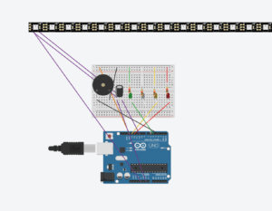
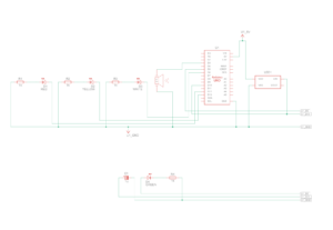
the circuit is very close to the reality (the pins are right). One big difference is that the LED strip is much bigger (in number of pixels).
//SOUND!
const int songspeed = 1.5; //Change to 2 for a slower version of the song, the bigger the number the slower the song
//*****************************************
#define NOTE_C4 262 //Defining note frequency
#define NOTE_D4 294
#define NOTE_E4 330
#define NOTE_F4 349
#define NOTE_G4 392
#define NOTE_A4 440
#define NOTE_B4 494
#define NOTE_C5 523
#define NOTE_D5 587
#define NOTE_E5 659
#define NOTE_F5 698
#define NOTE_G5 784
#define NOTE_A5 880
#define NOTE_B5 988
//*****************************************
int notes[] = { //Note of the song, 0 is a rest/pulse
NOTE_E4, NOTE_G4, NOTE_A4, NOTE_A4, 0,
NOTE_A4, NOTE_B4, NOTE_C5, NOTE_C5, 0,
NOTE_C5, NOTE_D5, NOTE_B4, NOTE_B4, 0,
NOTE_A4, NOTE_G4, NOTE_A4, 0,
NOTE_E4, NOTE_G4, NOTE_A4, NOTE_A4, 0,
NOTE_A4, NOTE_B4, NOTE_C5, NOTE_C5, 0,
NOTE_C5, NOTE_D5, NOTE_B4, NOTE_B4, 0,
NOTE_A4, NOTE_G4, NOTE_A4, 0,
NOTE_E4, NOTE_G4, NOTE_A4, NOTE_A4, 0,
NOTE_A4, NOTE_C5, NOTE_D5, NOTE_D5, 0,
NOTE_D5, NOTE_E5, NOTE_F5, NOTE_F5, 0,
NOTE_E5, NOTE_D5, NOTE_E5, NOTE_A4, 0,
NOTE_A4, NOTE_B4, NOTE_C5, NOTE_C5, 0,
NOTE_D5, NOTE_E5, NOTE_A4, 0,
NOTE_A4, NOTE_C5, NOTE_B4, NOTE_B4, 0,
NOTE_C5, NOTE_A4, NOTE_B4, 0,
NOTE_A4, NOTE_A4,
//Repeat of first part
NOTE_A4, NOTE_B4, NOTE_C5, NOTE_C5, 0,
NOTE_C5, NOTE_D5, NOTE_B4, NOTE_B4, 0,
NOTE_A4, NOTE_G4, NOTE_A4, 0,
NOTE_E4, NOTE_G4, NOTE_A4, NOTE_A4, 0,
NOTE_A4, NOTE_B4, NOTE_C5, NOTE_C5, 0,
NOTE_C5, NOTE_D5, NOTE_B4, NOTE_B4, 0,
NOTE_A4, NOTE_G4, NOTE_A4, 0,
NOTE_E4, NOTE_G4, NOTE_A4, NOTE_A4, 0,
NOTE_A4, NOTE_C5, NOTE_D5, NOTE_D5, 0,
NOTE_D5, NOTE_E5, NOTE_F5, NOTE_F5, 0,
NOTE_E5, NOTE_D5, NOTE_E5, NOTE_A4, 0,
NOTE_A4, NOTE_B4, NOTE_C5, NOTE_C5, 0,
NOTE_D5, NOTE_E5, NOTE_A4, 0,
NOTE_A4, NOTE_C5, NOTE_B4, NOTE_B4, 0,
NOTE_C5, NOTE_A4, NOTE_B4, 0,
//End of Repeat
NOTE_E5, 0, 0, NOTE_F5, 0, 0,
NOTE_E5, NOTE_E5, 0, NOTE_G5, 0, NOTE_E5, NOTE_D5, 0, 0,
NOTE_D5, 0, 0, NOTE_C5, 0, 0,
NOTE_B4, NOTE_C5, 0, NOTE_B4, 0, NOTE_A4,
NOTE_E5, 0, 0, NOTE_F5, 0, 0,
NOTE_E5, NOTE_E5, 0, NOTE_G5, 0, NOTE_E5, NOTE_D5, 0, 0,
NOTE_D5, 0, 0, NOTE_C5, 0, 0,
NOTE_B4, NOTE_C5, 0, NOTE_B4, 0, NOTE_A4
};
//*****************************************
int duration[] = { //duration of each note (in ms) Quarter Note is set to 250 ms
125, 125, 250, 125, 125,
125, 125, 250, 125, 125,
125, 125, 250, 125, 125,
125, 125, 375, 125,
125, 125, 250, 125, 125,
125, 125, 250, 125, 125,
125, 125, 250, 125, 125,
125, 125, 375, 125,
125, 125, 250, 125, 125,
125, 125, 250, 125, 125,
125, 125, 250, 125, 125,
125, 125, 125, 250, 125,
125, 125, 250, 125, 125,
250, 125, 250, 125,
125, 125, 250, 125, 125,
125, 125, 375, 375,
250, 125,
//Rpeat of First Part
125, 125, 250, 125, 125,
125, 125, 250, 125, 125,
125, 125, 375, 125,
125, 125, 250, 125, 125,
125, 125, 250, 125, 125,
125, 125, 250, 125, 125,
125, 125, 375, 125,
125, 125, 250, 125, 125,
125, 125, 250, 125, 125,
125, 125, 250, 125, 125,
125, 125, 125, 250, 125,
125, 125, 250, 125, 125,
250, 125, 250, 125,
125, 125, 250, 125, 125,
125, 125, 375, 375,
//End of Repeat
250, 125, 375, 250, 125, 375,
125, 125, 125, 125, 125, 125, 125, 125, 375,
250, 125, 375, 250, 125, 375,
125, 125, 125, 125, 125, 500,
250, 125, 375, 250, 125, 375,
125, 125, 125, 125, 125, 125, 125, 125, 375,
250, 125, 375, 250, 125, 375,
125, 125, 125, 125, 125, 500
};
int redLED = 12;
int yellowLED = 13;
int whiteLED = 6;
int greenLED = 5;
int buzzer = 3;
int redState = -1;
int yellowState = -1;
int whiteState = -1;
int greenState = -1;
//definitions for the LEDS
#include <FastLED.h>
#define LED_PIN 10
#define NUM_LEDS 54
#define BRIGHTNESS 64
#define LED_TYPE WS2811
#define COLOR_ORDER GRB
CRGB leds[NUM_LEDS];
#define UPDATES_PER_SECOND 100
CRGBPalette16 currentPalette;
TBlendType currentBlending;
extern CRGBPalette16 myRedWhiteBluePalette;
extern const TProgmemPalette16 myRedWhiteBluePalette_p PROGMEM;
void setup() {
//pinMode(redLED, OUTPUT);
//pinMode(yellowLED, OUTPUT);
//pinMode(whiteLED, OUTPUT);
//pinMode(greenLED, OUTPUT);
//pinMode(buzzer, OUTPUT);
pinMode(redLED, INPUT_PULLUP);
pinMode(yellowLED, INPUT_PULLUP);
pinMode(whiteLED, INPUT_PULLUP);
pinMode(greenLED, INPUT_PULLUP);
pinMode(buzzer, INPUT_PULLUP);
Serial.begin(9600);
delay( 3000 ); // power-up safety delay
FastLED.addLeds<WS2812, LED_PIN, RGB>(leds, NUM_LEDS);
FastLED.setBrightness( BRIGHTNESS );
currentPalette = RainbowStripeColors_p;
currentBlending = LINEARBLEND;
}
void loop() {
digitalWrite(redLED, LOW);
digitalWrite(yellowLED, LOW);
digitalWrite(whiteLED, LOW);
digitalWrite(greenLED, LOW);
redState= digitalRead(redLED);
Serial.print(“red “);
Serial.println(redState);
if (redState == 0){
//digitalWrite(redLED, HIGH);
leds[43] = CRGB(0,255,0);
leds[42] = CRGB(0,255,0);
FastLED.show();
tone(buzzer, 800);
delay(1000);
noTone(buzzer);
//digitalWrite(redLED, LOW);
}
else{
noTone(buzzer);
leds[43] = CRGB(0,0,0);
leds[42] = CRGB(0,0,0);
FastLED.show();
}
yellowState = digitalRead(yellowLED);
Serial.print(“yellow “);
Serial.println(yellowState);
if (digitalRead(yellowLED) == 0){
//digitalWrite(yellowLED, HIGH);
tone(buzzer, 600);
leds[46] = CRGB(255, 255 ,0);
leds[45] = CRGB(255, 255, 0);
FastLED.show();
delay(1000);
noTone(buzzer);
//digitalWrite(yellowLED, LOW);
}
else{
noTone(buzzer);
leds[46] = CRGB(0,0,0);
leds[45] = CRGB(0,0,0);
FastLED.show();
}
whiteState = digitalRead(whiteLED);
Serial.print(“white “);
Serial.println(whiteState);
if (whiteState == 0){
//digitalWrite(whiteLED, HIGH);
leds[48] = CRGB(255,255,255);
leds[49] = CRGB(255,255,255);
FastLED.show();
tone(buzzer, 400);
delay(1000);
noTone(buzzer);
//digitalWrite(whiteLED, LOW);
}
else{
noTone(buzzer);
leds[48] = CRGB(0,0,0);
leds[49] = CRGB(0,0,0);
FastLED.show();
}
greenState = digitalRead(greenLED);
Serial.print(“green “);
Serial.println(greenState);
if (greenState == 0){
//digitalWrite(greenLED, HIGH);
leds[51] = CRGB(255,0,0);
leds[52] = CRGB(255,0,0);
FastLED.show();
tone(buzzer, 200);
delay(1000);
noTone(buzzer);
//digitalWrite(greenLED, LOW);
}
else{
noTone(buzzer);
leds[51] = CRGB(0,0,0);
leds[52] = CRGB(0,0,0);
FastLED.show();
}
if (redState == 0 && yellowState == 0 && whiteState == 0 && greenState == 0){
int color = 0;
for (int i=0;i<203;i++){
int k = 0;
uint8_t brightness = 255;
int wait = duration[i] * songspeed;
tone(buzzer,notes[i],wait);
delay(wait);
if (i < 56){
leds[i] = CHSV(color, 255, 255); /* The higher the value 4 the less fade there is and vice versa */
color+=4;
FastLED.show();
}
else if (i – 56 < 56){
leds[i-56] = CHSV(color, 255, 255); /* The higher the value 4 the less fade there is and vice versa */
color+=4;
FastLED.show();
}
else if (i < 112 < 56){
leds[i-112] = CHSV(color, 255, 255); /* The higher the value 4 the less fade there is and vice versa */
color+=4;
FastLED.show();
}
else {
leds[i-168] = CHSV(color, 255, 255); /* The higher the value 4 the less fade there is and vice versa */
color+=4;
FastLED.show();
}
}
}
}
//leds[2] = CRGB(0,255,0);
//leds[3] = CRGB(0,0,255);
// leds[4] = CRGB(0,0,255);
// leds[5] = CRGB(0,0,255);
// leds[6] = CRGB(0,0,0);


