due to my absence on the actual recitation that took place on friday 16th, i attended a meeting with Lydia, interaction lab learning assistant so that i can catch up with the work!
as i have only attended interaction lab once (this week) i only saw LED, wires, breadboard and resistor in action. i have also went through the multimeter with professor Gottfried and probably much more, however didn’t remember much straightaway. so, when it came to picking up the needed materials, i sought help from Lydia:) e.g. when i saw a variable resistor i didn’t even know how to connect it and what should i do with it. i diverge. as needed, i started with the task 1.
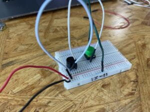
task 1: step 1
built it almost from the first try. Lydia helped me to understand how am i supposed to connect the button to the circuit (turns out if i connect two non-diagonal parts with a wire it doesn’t work, wow). so, after a small struggle i was able to complete the task. 
*in retrospective, i probably could have used a bit less wires for it too look more decent, but at the time i didn’t know that i am going to build on on this structure.
task 1: step 2
task 2 started with the realization that it is basically a build-up for the task 1. sadly, this realization came after i already deconstructed the task 1 circuit. so i had to reassemble it again (took me a minute) and then started to do the task 2. shortly, i completed the task. the only problem i encountered was that i forgot that the LED’s long leg is supposed to go from the “+” charge, which i din’t notice i put in the “-“. Lydia reminded me of that and i got it fixed pretty quickly. so, my circuit worked perfectly again.
again, probably could’ve used less wires. however my decision to move the LED on the other side worked out perfectly as in further steps it became easier to connect the variable resistor. here, i also consulted with Lydia regarding reading a circuit scheme and she helped me to understand the algorithm of building one (usually start from the outer lap and then step-by-step build the inner laps).
task 1: step 3
the third step was quite easy, except for figuring out the variable resistor as it took me some googling to find out how to connect it properly (that one leg should be connected to the +, another to the – and the middle one to the object (LED in this case)).
only after assembling it i realized what the variable resister actually was doing (varying the potential charge going through the LED). it didn’t stop me from building it though, so i believe it is fine. also, less wires next time (going to try).
task 2
as for the second task, Lydia showed me what i was supposed to make and walked me through the steps. doing the soldering was probably the hardest part, however as i had some previous
knowledge and some skill (two years ago i tried soldering at school) it didn’t take me too much time to figure out what to do. and then i connected the wires to the breadboard and finished the circuit! I personally really liked this DIY part as it made the whole work a tiny bit more personal and handy!
I didn’t really had a partner to complete the morse code thing, but i hope it is fine! the fun part wasn’t that important to the circuit anyway!
additional questions
- Question 1: What is the function of the resistor R1? (You can read about the reason why LEDs need resistors here)
The function of the resistor is to limit the amount of current (that comes from the power source) to a value that is in the range of LED’s forward current ratings (not higher for sure). Because usually the range of the LED’s forward current is lower than 5V and we usually use 5V power source. If we don’t use resistors the LED will burn out.
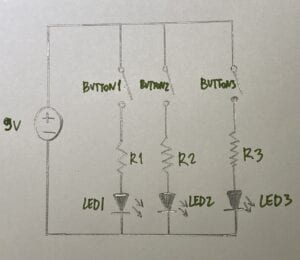
- Question 2: Looking at the following circuit, draw its diagram by yourself.
*not sure about the labels

- Question 3: After reading The Art of Interactive Design, in what way do you think that the circuit you built today includes interactivity? Which degree of interactivity does it possess? Please explain your answer.
I believe that the circuit that we build today includes three main ways of how we receive information: we can listen to the buzzer (if its on – it means the circuit is active), then we can touch it (as it reacts to when the button is pressed + when we use variable resistor to dim or brighten the second LED), and we can also see the change in the LED’s behavior when the button is pressed. we can’t really speak to it, however we can use it to speak Morse code, which should definitely count for something! overall, i believe this pretty much prosaic system is quite interactive, while having quite a limited number of its state variations (buzz on/of (long/short), light on/of, dimmed light/bright light).
- Question 4: How can Interaction Design and Physical Computing be used to create Interactive Art? You can reference Zack Lieberman’s video or any other artists that you know.
I believe that using Physical computing (a bit more advanced ones though than we used today, such as scanners or trackers of movement, eyesight, voice, face expressions) there are numerous ways of creating something quite extraordinary as any human will be attracted to something that reacts to it (especially if it is some engaging, intriguing way). For example the clothing that was reacting to the direction of the person’s view. i believe that it is such an interactive and novel idea!