In this recitation, I browsed a laser-cutting website to fabricate/design two different shapes. When combined together, a visually-appealing pattern would be created. I worked with my partner Sid in this recitation! Below, I will document our progress and how we worked through each step.
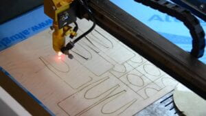
Step 1: Design
First, we logged on to cuttle.xyz, a design tool for digital cutting machines. Luckily, we learned in the last recitation a basic introduction of the program. Our first task was to build a sculpture, with each one of us designing half of a part. Here, a simple stand was the goal, as it would allow our eventual sculpture to be propped up.
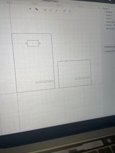
Carefully following the instructions, I began to craft the piece. As there were two designs made to combine into one, my partner and I separately worked on building it. I chose to be ‘Student B’, and followed the instructed route. I changed the unit settings from inches to millimeters. Furthermore, I enabled grid snapping, & created an (80mm-60mm) rectangle. I also used the ’round corners’ feature, which I found especially neat for the final laser-cutted result. After this, I created another (40 mm- 2.8 mm tall) rectangle. I placed it on the right side edge of the first rectangle. In other words, this allowed for two pieces of wood to intersect with each other and create the stand insertion.
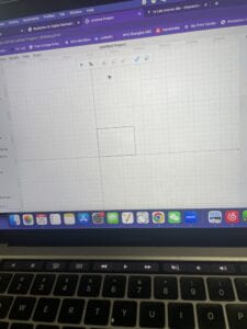
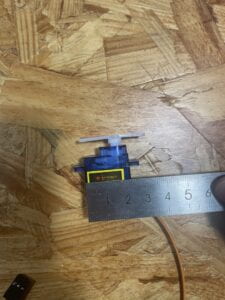
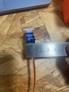
My partner, Sid, followed similar instructions and created a piece that connected with mine. I helped measure the width & depth (32mm & 13mm) of the servo motor, along with its servo screw hole diameter and its distance from the inside edge. After this, I reported the measurements to Sid. He then inserted these measurements to create the servo hole proportion. Sharing and merging the two files together, we now had successfully completed the stand!
Step 1.2: Pattern Design
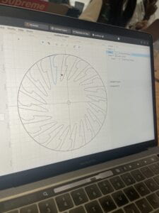
Moving on, we wanted to each create a pattern with an interference visual effect. Creating from scratch a circular pattern (120 mm diameter), I used my visual instincts to guide the idea of my shape. I first used ‘path’ from the pen ‘feature’ to create a simple but pretty hill pattern. Then, I used a rotational repeat to expand its beauty. Assigning each other roles, I decided my design to be static. Therefore, I added a center rectangle (32.5 x 12.5 mm) for the servo to go through. My partner Sid’s design consequently would be moving. His design would be attached to the shaft of the servo (created a center hole with a diameter of 4.5mm), allowing it to spin!
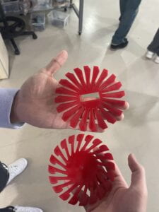
Lastly, we exported our designs and waited for them to print! I attempted to make my shape clockwise, with Sid’s being counter-clockwise. Furthermore, his design resembles that of a knife! We wanted a fidget spinner effect, so it looked mesmerizing if spun at high speed. Below, is the online visualization of the two designs.
(My Design) 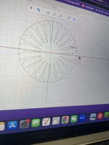
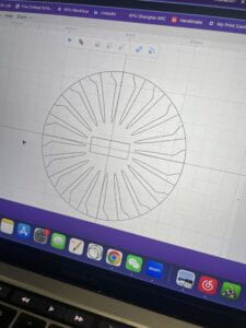
(Sid’s Design) 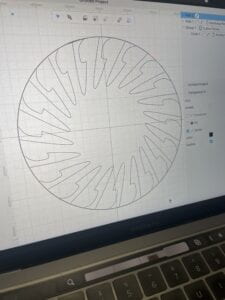 .
. 
Step 2: Laser Cut
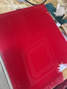
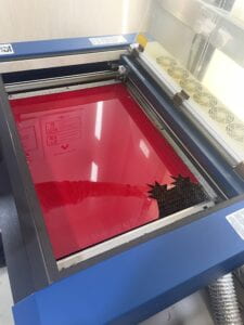
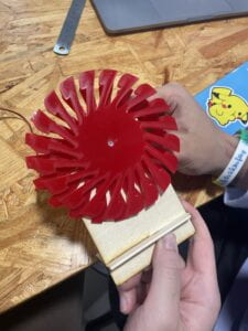
With the previous design being built, the rest was not too difficult. Walking to the fabrication lab, we viewed our design being produced in the laser cutter. The machine looked scary, but extremely advanced at the same time. Choosing the board we wanted, we used a red board to give the ‘knives’ a scarier effect. Professor Andy allowed us to view the machine at work, which was eye-opening. After a couple of minutes, we successfully had our beautiful designs precisely cut out!
Step 3: Assemble
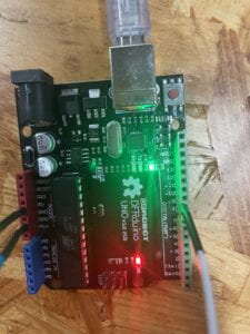
Finally, we had all the physical parts completed! We gathered our two circular designs, along with the stand that we connected together. All we had to do now was assemble the stand with the servo and circular patterns. Connecting Arduino with the servo motor, I wired jumper cables from 5V, GND, & pin 9 to the three ports in the servo motor. Then, I ran the Servo Sweep example, allowing the motor to easily spin.
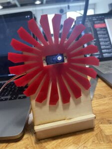
Mounting my static piece on the stand, though, was not an easy task. We attempted to use small screws to tighten it, but realized it was still too loose. With no screwdrivers around, we decided to use tape as a simple alternative. I mounted Sid’s moving design to the sweeping motor. At last, our teamwork had worked and the pieces spun! The designs overlapped each other, creating this wonderful knife-spinning pattern. We played around with the delay speed, but there were little to no differences. Overall, I loved this recitation and laser cutting. I think it’s super interesting that a machine can recreate patterns with such precision. I hope to polish my laser-cutting skills so that I can design more intricate devices in the future!
Code:
/* Sweep
by BARRAGAN <http://barraganstudio.com>
This example code is in the public domain.
modified 8 Nov 2013
by Scott Fitzgerald
https://www.arduino.cc/en/Tutorial/LibraryExamples/Sweep
*/
#include <Servo.h>
Servo myservo; // create servo object to control a servo
// twelve servo objects can be created on most boards
int pos = 0; // variable to store the servo position
void setup() {
myservo.attach(9); // attaches the servo on pin 9 to the servo object
}
void loop() {
for (pos = 0; pos <= 180; pos += 1) { // goes from 0 degrees to 180 degrees
// in steps of 1 degree
myservo.write(pos); // tell servo to go to position in variable 'pos'
delay(15); // waits 15 ms for the servo to reach the position
}
for (pos = 180; pos >= 0; pos -= 1) { // goes from 180 degrees to 0 degrees
myservo.write(pos); // tell servo to go to position in variable 'pos'
delay(15); // waits 15 ms for the servo to reach the position
}
}
Leave a Reply