In this recitation, I used Processing and Arduino again to create interactive activities! During this recitation, I created an Etch-A-Sketch (childhood nostalgia) from the two programs, and a screen that displayed a constantly moving ball! Below, I will expand on each task and the procedures I used to complete them.

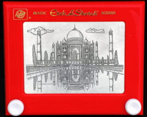
Task #1: Make a Processing Etch-A-Sketch
In this task, I made a processing Etch-A-Sketch myself. First, we needed to send two analog values (Arduino) and connect them to Processing. To do this, I built a circuit using two potentiometers (as shown in the last class). Then, I wrote an Arduino code that read the values, then corresponded by sending them serially. Below, the first picture is the 10K potentiometer that is received in our kit. Though, I ended up switching them to the B10K potentiometer.
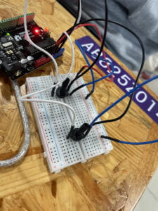
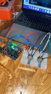
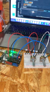
Testing to see if the analog values were sent, I examined the serial monitor in the Arduino ‘SendMultipleValues’ example to see if values were present. Indeed, they were! Below, the left potentiometer created the left value and vice versa. Here is a visual example:
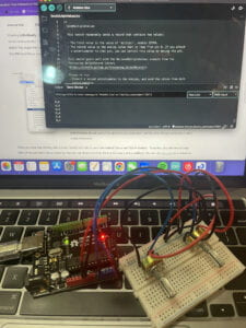
Then, I wrote a Processing code that modified a circle’s x and y values depending on the potentiometer that was tested. Similarly, I used Arduino to help communicate and work along this process. As a basis, I started with the Arduino example code, then slowly refined it. I added the SensorValue’s as an integer variable, stating them as ‘A0’ & ‘A5’ (location of my wiring). By doing this, I now could have values for both of my potentiometers (original code only had one). When done, this allowed me to create a prototype Etch-A-Sketch using circles.
Arduino Code:
#include "SerialRecord.h"// Change this number to send a different number of valuesSerialRecord writer(2);void setup() {Serial.begin(9600);pinMode(6, INPUT);}void loop() {int sensorValue1 = analogRead(A0);int sensorValue2 = analogRead(A5);writer[0] = sensorValue1;writer[1] = sensorValue2;writer.send();// This delay slows down the loop. This can make it easier to debug the// program.delay(10);}import processing.serial.*;import osteele.processing.SerialRecord.*;Serial serialPort;
SerialRecord serialRecord;
void setup() {
size(500, 500);
String serialPortName = SerialUtils.findArduinoPort();
serialPort = new Serial(this, serialPortName, 9600);
// If the Arduino sketch sends a different number of values, modify the number
// `2` on the next line to match the number of values that it sends.
serialRecord = new SerialRecord(this, serialPort, 2);
}
void draw() {
//background(0);
serialRecord.read();
int value1 = serialRecord.values[0];
int value2 = serialRecord.values[1];
float x = map(value1, 0, 1024, 0, width);
float y = map(value2, 0, 1024, 0, height);
circle(x, y, 20);
}
After this, I modified the existing code to use lines instead of circles. This allows for a more authentic Etch-A-Sketch effect. Here, I used the same Arduino code (SendMultipleCode example), but added a new code into Processing (RecieveMultipleValues example). As can be seen, I took away the millis() as it was unnecessary. Also, I added ‘pa’ and ‘pb’ as float variables with the value of zero. Lastly, the previous ‘circle()’ just had to be changed to ‘line()’. By doing all of these adjustments, the line could be constructed instead of the circles. Now, we had an Etch-A-Sketch at work! By adjusting both of the potentiometers, one representing x-axis and one representing y-axis, simple words or forms can be created. Also, the color of the line and background be easily be changed to fit a person’s preferences. With that, task 1 is sucessfully completed. A reflection would be that mostly everything went well here with minimum surprises. It was difficult switching between Processing & Arduino, especially with different tabs open. Therefore, management is important in keeping codes organized. The interaction involved was again, using the two potentiometers (X,Y) as a DIY Etch-A-Sketch.
Below, is an video of it in both white & black:
Arduino Code:
#include "SerialRecord.h"
// Change this number to send a different number of values
SerialRecord writer(2);
void setup() {
Serial.begin(9600);
pinMode(6, INPUT);
}
void loop() {
int sensorValue1 = analogRead(A0);
int sensorValue2 = analogRead(A5);
writer[0] = sensorValue1;
writer[1] = sensorValue2;
writer.send();
// This delay slows down the loop. This can make it easier to debug the
// program.
delay(10);
}
Processing Code:
import processing.serial.*;
import osteele.processing.SerialRecord.*;
Serial serialPort;
SerialRecord serialRecord;
float pa;
float pb;
void setup() {
background(255);
size(500, 500);
String serialPortName = SerialUtils.findArduinoPort();
serialPort = new Serial(this, serialPortName, 9600);
// If the Arduino sketch sends a different number of values, modify the number
// `2` on the next line to match the number of values that it sends.
serialRecord = new SerialRecord(this, serialPort, 2);
pa = 0;
pb = 0;
}
void draw() {
serialRecord.read();
int value1 = serialRecord.values[0];
int value2 = serialRecord.values[1];
float x = map(value1, 0, 1024, 0, width);
float y = map(value2, 0, 1024, 0, height);
//circle(x, y, 20);
line(x, y, pa, pb);
pa = x;
pb = y;
stroke(0);
}
Task #2: Bouncing Ball
Here, I worked with my partner Calvin Lin to complete this task. Since this task is different from the last, we unwired everything and started from scratch. Using the 9G servo motor, we wired it to our Arduino. This summed up the Arduino portion, with little to no interactive elements for the user itself.
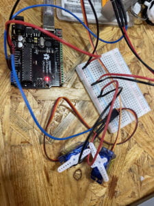
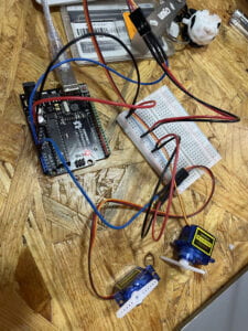
Now that we have the servo motor working, we wanted to display in somehow via Processing. The goal was to create a ball that moves horizontally, then when connected with the edge of the screen, gave some form of indication (this case being the servo motors twisting in its direction). This task was pretty difficult, as there were little to no references or clear instructions given. A lot of it was visually a plan and executing it using different concepts implemented. Below, after a long-amount of constant tinkering, are the two codes:
Arduino:
#include "SerialRecord.h"
#include <Servo.h>
Servo left; // create servo object to control a servo
Servo right;
int motor = -1;
// Change this number to the number of values you want to receive
SerialRecord reader(1);
void setup() {
Serial.begin(9600);
right.attach(A0);
left.attach(A1);
}
void loop() {
if (reader.read()) {
motor = reader[0];
}
if (motor==1) {
left.write(90);
delay(500);
left.write(0);
motor = -1;
}
if (motor==0) {
right.write(90);
delay(500);
right.write(0);
motor = -1;
}
}
Processing Code:
import processing.serial.*;
import osteele.processing.SerialRecord.*;
float x;
float y;
float i=0;
boolean left = true;
boolean right = false;
int edge = 0;
Serial serialPort;
SerialRecord serialRecord;
void setup() {
fullScreen();
String serialPortName = SerialUtils.findArduinoPort();
serialPort = new Serial(this, serialPortName, 9600);
serialRecord = new SerialRecord(this, serialPort, 1);
//serialRecord.logToCanvas(false);
}
void draw() {
//println(frameRate);
background(0);
if (i<=0) {
left = true;
right = false;
}
if (i>=0.95*width && edge==0) {
serialRecord.values[0] = 1;
serialRecord.send(); // send it!
edge = 1;
}
if (i<=0.05*width && edge==1) {
serialRecord.values[0] = 0;
serialRecord.send(); // send it!
edge = 0;
}
if (i>=width) {
right = true;
left = false;
}
if (left==true) {
i = lerp(i, 1.1*width, 0.02);
}
if (right==true) {
i = lerp(i, -0.1*width, 0.02);
}
fill(255);
circle(i, height/2, 70);
}
First, let’s analyze the Arduino code and how it operates. There are two ‘if’ statements, one for the left servo and the another for the right. By setting and creating two different Servo motors variables, this can be done. Other than that, the code is pretty straightforward. If the motor hit/activated the 1 value, the right servo would move to virtually ‘hit’ the ball. Then, the ball would bounce back to the original start position of 0. Again, the left servo would detect this and ‘hit’ the ball back to 1. This would become an infinite process as it loops over and over again.
In the Processing code, this is where it gets a little complicated. There were different variables involved (float, boolean, int). First, we added the fullScreen() function to make the sketch automatically fullscreen every time. However, I found this to be quite inconvenient as if the code had mistakes, the beach ball of death would happen and create a frozen screen. Also, we used a new ‘lerp’ function to set the range [start..end] based on a set parameter (typically within a [0..1] range). With guidance from the LA’s, we were able to slowly but surely recreate this sketch. After tedious work and time, we were able to create it and complete this task!
For sure, this had to be one of the most challenging tasks to date. We had to worry about both Arduino & Processing aspects while using various codes and functions to connect everything together. If I could change this task to be more interactive, I would propose perhaps adding a ‘button’ that also served as a pin when hit. If the ball was close enough when the button is clicked, it would successfully bounce back. By doing this, this task would resemble an interactive game. In conclusion, this recitation was time-consuming but rewarding! We had to learn more knowledge about the two platforms, and how easily they can be interchanged (Arduino to Processing — Processing to Arduino).
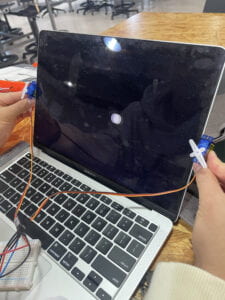
Examples:
Leave a Reply