In this recitation, I successfully combined Arduino and Processing together! In the last recitation, I look forward to combining these two elements together. During this recitation, I used a NeoPixel Led strip to create light animations for one of my favorite music pieces! Below, I will explain the process that it took, including any difficulties and hardships faced. Now, let’s ‘slowly dance in the dark’!
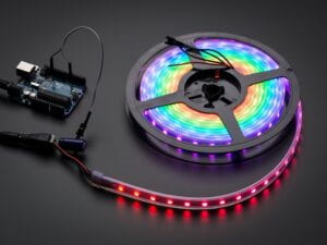
Materials:
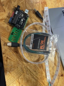
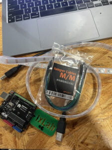
- 1 * Arduino Uno
- 1 * USB A to B cable
- 3 * jumper cables M/M
- 1 * NeoPixel strip (WS2812B – Individually Addressable LEDs)
Task #1: Test the NeoPixel
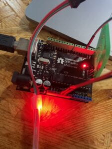
First, I had to connect the NeoPixel strip itself, to the Arduino. This felt kind of nostalgic as I haven’t used Arduino in a long time. Following the schematic diagram, I plugged in a green M/M wire to pin 3. Following that, I plugged in a red M/M wire to the 5V and a black M/M wire to GND. Soon, my circuit would be complete!
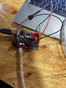
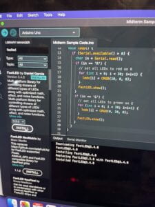
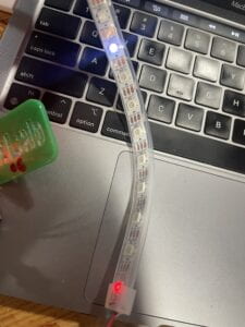
Now, I had to download libraries so that the code could work efficiently. So, I downloaded “FastLed” library by Daniel Garcia. To ensure the NeoPixel would work properly, I tested it to run. It did ~ I got a blinking flashing red light, which signified the Arduino code working! Below is a quick representation of how the NeoPixel light is currently supposed to look.
Task #2: Using Computer to Light Up NeoPixels
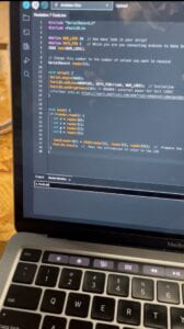
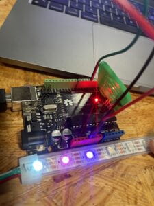
In this task, the objective is pretty straightforward again. I followed each instruction in chronological order, & was able to finish this task quickly. First, I downloaded the SerialRecord library contributed by Oliver Steele. This library allowed me to send and receive multiple-values records on the serial port. After this, I used the code that combined both the FastLed and SerialRecord libraries together. To test this code, we had to put in 4 values on the serial monitor in Arduino. The 4 values stand as stated in recitation, ” . . . the first parameter will indicate the pixel number, the second the content of red color, then green, and last blue” (Interaction Lab). Hence, the numbers should look like (x, r, g, b). By putting in different numbers, it will mix the shades of RBG’s together to create different colors. Below, are some variations and colors that I tweaked!
Now, we’ve successfully set up Arduino. Therefore, let’s move on to interaction on screen (Processing)! Using another code provided here, I programmed the Processing sketch. At first, it didn’t work at first. However, I figured that this was due to my serial monitor in Arduino not being closed. Not that the port wasn’t busy anymore, I could have both codes running! Essentially, Processing told Arduino how to run, then Arduino listen to this information & interacted using the NeoPixel lights. Below, I have an example of how it looked now! It was extremely interesting viewing the two programs going hand-in-hand together.
After a little tinkering and playing around, I could interact with any corresponding light depending on the direction in that I point my mouse. This is possible due to the following code:
if (mousePressed == true) {
int n = floor(constrain(mouseX/W , 0, NUM-1));
As I press my mouse in a certain area, the color should correspond, given support with the other functions in the code.
Task #3: Add Music!
Finally, the last but most challenging task was the add music! This was not an easy part to do, as it required both codes to be mashed together (to create a visualization on the screen & on the NeoPixel strip). Now, I had to begin picking a music choice and officially begin ‘DJ Tuning’! Instead of beat.aiff, I decided to use my favorite song, called ‘Slow Dancing in the Dark’ by Joji. Taking the link from Youtube, I used an online converter to change it into an MP3 file.


The longest part was combining the code together, as I had to constantly switch code in between the two tabs. I had to differentiate what went before void setup(), in void setup(), & everything that happened in void draw(). After spending nearly thirty minutes, I finally got the hang of it! The squares would jump depending on the volume of sound. If it was louder, it would go on the right side (vice versa). This looked something like this:
Code:
import processing.serial.*;
import osteele.processing.SerialRecord.*;
import processing.sound.*;
Serial serialPort;
SerialRecord serialRecord;
SoundFile sample;
Amplitude analysis;
int W; //width of the tiles
int NUM = 30; //amount of pixels
int[] r = new int[NUM]; //red of each tile
int[] g = new int[NUM]; //red of each tile
int[] b = new int[NUM]; //red of each tile
void setup() {
size(640, 480);
W = width/NUM;
// You can use this syntax and change COM3 for your serial port
// printArray(Serial.list());
// serialPort = new Serial(this, "COM3", 9600);
// in MacOS it looks like "/dev/cu.usbmodem1101"
//or you can try to use this instead:
String serialPortName = SerialUtils.findArduinoPort();
serialPort = new Serial(this, serialPortName, 9600);
serialRecord = new SerialRecord(this, serialPort, 4);
serialRecord.logToCanvas(false);
rectMode(CENTER);
// load and play a sound file in a loop
sample = new SoundFile(this, "658586__josefpres__piano-loops-051-octave-up-short-loop-120-bpm.wav");
sample.loop();
// create the Amplitude analysis object
analysis = new Amplitude(this);
// analyze the playing sound file
analysis.input(sample);
}
void draw() {
println(analysis.analyze());
background(125, 255, 125);
noStroke();
fill(255, 0, 150);
// analyze the audio for its volume level
float volume = analysis.analyze();
// volume is a number between 0.0 and 1.0
// map the volume value to a useful scale
float diameter = map(volume, 0, 1, 0, width);
// draw a circle based on the microphone amplitude (volume)
circle(width/2, height/2, diameter);
//if the volume if greater than x, turn the middle pixel red
if (volume > 0.10) {
serialRecord.values[0] = 15; // which pixel we change (0-59)
serialRecord.values[1] = 255; // how much red (0-255)
serialRecord.values[2] = 0; // how much green (0-255)
serialRecord.values[3] = 0; // how much blue (0-255)
serialRecord.send(); // send it!
}
if (volume < 0.10){
serialRecord.values[0] = 15; // which pixel we change (0-59)
serialRecord.values[1] = 255; // how much red (0-255)
serialRecord.values[2] = 100; // how much green (0-255)
serialRecord.values[3] = 100; // how much blue (0-255)
serialRecord.send(); // send it!
}
}
Step 4: Have Fun
Now, I successfully combined both elements (Processing & Arduino) together! The squares would change color when clicked depending on their location. However, I was thinking of another element to combine, one that was creative and made sense. Therefore, I thought about using the frequency analysis code, which tested the input volume sound and drew corresponding circles with it (the louder the noise, the bigger the circle). The sample code was through my own voice, however, I wanted it to be through the sound of the song.
Again, I now added a third element into the code. Other than the serialPort and amplitude analysis, I now had frequency analysis as well. This took a little bit of time to tweak, but it still worked in the end! Though, I noticed that the effects were sub-par. Now, the song could continue playing, with the mouse switching colors of the Neo-Pixel. Also, if the screen was clicked again, the background would change to white (as I set) & the frequency analysis would appear. The issue is that it is extremely choppy, as the frequency would sometimes freeze completely, then resume on its after around a second. I think this is due to multiple elements begin done simultaneously, which creates this problem. I think that this is hard to tweak, but still visually appealing. In conclusion, I think this was a great recitation and I learned a lot! I combined codes together, & got to play a beautiful melody. I look forward to the next recitation where Arduino interaction would translate onto the Processing screen!
Note: Needs a special folder to open and play correctly! There should be a folder with the code, followed by a sub-folder with the mp3/sound file. Only then, can Processing find the music and play it. Below, is the audio source.
Code:
import processing.serial.*;
import osteele.processing.SerialRecord.*;
import processing.sound.*;
Serial serialPort;
SerialRecord serialRecord;
SoundFile sample;
Amplitude analysis;
// declare an AudioIn object
AudioIn microphone;
// declare an Frequency analysis object to detect the frequencies in a sound
FFT freqAnalysis;
// declare a variable for the amount of frequencies to analyze
// should be a multiple of 64 for best results
int frequencies = 1024;
// Define the frequencies wanted for our visualization. Above that treshold frequencies are rarely atteigned and stay flat.
int freqWanted = 128;
// declare an array to store the frequency anlysis results in
float[] spectrum = new float[freqWanted];
// Declare a drawing variable for calculating the width of the
float circleWidth;
int W; //width of the tiles
int NUM = 60; //amount of pixels
int[] r = new int[NUM]; //red of each tile
int[] g = new int[NUM]; //red of each tile
int[] b = new int[NUM]; //red of each tile
void setup() {
size(640, 480);
W = width/NUM;
// You can use this syntax and change COM3 for your serial port
// printArray(Serial.list());
// serialPort = new Serial(this, "COM3", 9600);
// in MacOS it looks like "/dev/cu.usbmodem1101"
//or you can try to use this instead:
String serialPortName = SerialUtils.findArduinoPort();
serialPort = new Serial(this, serialPortName, 9600);
serialRecord = new SerialRecord(this, serialPort, 4);
serialRecord.logToCanvas(false);
rectMode(CENTER);
// load and play a sound file in a loop
sample = new SoundFile(this, "joji.mp3");
sample.loop();
// create the Amplitude analysis object
analysis = new Amplitude(this);
// analyze the playing sound file
analysis.input(sample);
//Frequency Analysis
// Calculate the width of the circles depending on how the bands we want to display.
circleWidth = width/float(freqWanted);
// create the AudioIn object and select the mic as the input stream
microphone = new AudioIn(this, 0);
// start the mic input without routing it to the speakers
microphone.start();
// create the Frequency analysis object and tell it how many frequencies to analyze
freqAnalysis = new FFT(this, frequencies);
// use the microphone as the input for the analysis
freqAnalysis.input(microphone);
}
void draw() {
println(analysis.analyze());
background(125, 255, 125);
noStroke();
fill(255, 0, 150);
// analyze the audio for its volume level
float volume = analysis.analyze();
// volume is a number between 0.0 and 1.0
// map the volume value to a useful scale
float diameter = map(volume, 0, 1, 0, width);
// draw a circle based on the microphone amplitude (volume)
circle(width/2, height/2, diameter);
//if the volume if greater than x, turn the middle pixel red
if (volume > 0.10) {
serialRecord.values[0] = 15; // which pixel we change (0-59)
serialRecord.values[1] = 255; // how much red (0-255)
serialRecord.values[2] = 0; // how much green (0-255)
serialRecord.values[3] = 0; // how much blue (0-255)
serialRecord.send(); // send it!
}
if (volume < 0.10) {
serialRecord.values[0] = 1; // which pixel we change (0-59)
serialRecord.values[1] = 255; // how much red (0-255)
serialRecord.values[2] = 100; // how much green (0-255)
serialRecord.values[3] = 100; // how much blue (0-255)
serialRecord.send(); // send it!
}
background(0);
for (int i=0; i<NUM; i ++) {
fill(r[i], g[i], b[i]);
rect(i * W + W/2, height/2, 10, 10);
}
if (mousePressed == true) {
int n = floor(map(volume, 0, 1, 0, 60));
r[n] = floor(random(255));
g[n] = floor(random(255));
b[n] = floor(random(255));
serialRecord.values[0] = n; // which pixel we change (0-59)
serialRecord.values[1] = r[n]; // how much red (0-255)
serialRecord.values[2] = g[n]; // how much green (0-255)
serialRecord.values[3] = b[n]; // how much blue (0-255)
serialRecord.send(); // send it!
// analyze the frequency spectrum and store it in the array
freqAnalysis.analyze(spectrum);
printArray(spectrum);
background(255);
fill(200, 0, 100, 150);
noStroke();
// draw circles based on the values stored in the spectrum array
// adjust the scale variable as needed
float scale = 1000;
for (int i=0; i<freqWanted; i++) {
circle(i*circleWidth, height/2, spectrum[i]*scale);
}
}
}
Leave a Reply