In this recitation, we continued to use ‘Processing’ to build our existing knowledge of the program! We had to design a cute poster to document the IMA Fall 22 End-Of-Semester Show event. Below, I will explain the entire process from beginning to end. The piece was completed in a span of days, as I had to constantly improve the code and learn various intricate concepts.

Finding the Reference
To start out with, I had to brainstorm potential ideas to create the design. Using this link, I was able to find creative graphic design Pinterest references. Scrolling through several other artworks, I finally landed on one that I felt matched my requirements. It looks as the following:
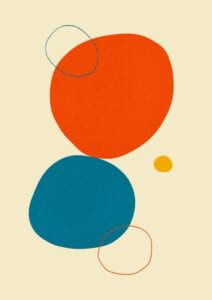
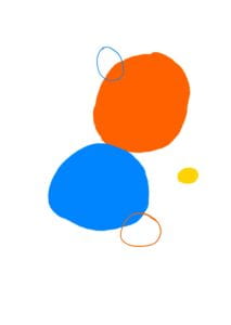
In the recitation post, it stated that the piece should ‘be composed of at least three basic shapes’. For me, this was an easy piece to recreate, merely using circles and tweaking its colors, size, & relative position – or so I thought. During the recitation, I wanted to focus on creating everything in the actual poster first. First, I drew out an example of what the artwork should resemble on my Ipad (attached above). Then, minute by minute, I attempted to craft the piece! By the end of the recitation, I had a product like this:
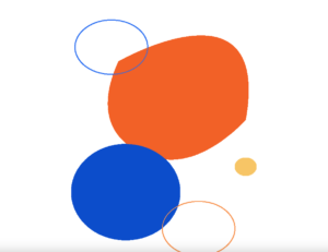
The code appears as follows:
void setup(){
size(1024, 768);
background(255);
strokeWeight(2);
stroke(255);
}
void draw(){
println(mouseX, mouseY);
noStroke();
fill(#F26127);
//beginShape();
beginShape();
vertex(380,240);
bezierVertex(380,240, 800,0,730,400);
vertex(730,400);
bezierVertex(730,400,600,550,470,500);
vertex(470, 500);
bezierVertex(470,500,280,460,380,240);
endShape();
fill(#0C4DCB);
ellipse(400, 600, 300, 265);
noFill();
stroke(#276BF0);
ellipse(360, 200, 200, 150);
stroke(#F79350);
ellipse(600, 700, 200, 150);
noStroke();
fill(#F7C566);
ellipse(730, 530, 60, 50);
}
In this code, I made the size ‘1024, 768’ as required by the prompt. I noticed that since some of the circles were pointy, so simple ellipses would not complete the job. Therefore, I learned the vertex & bezierVertex commands to plot the coordinates to their respective positions. To assist me with this step, I used the ‘println;’ command as it points out the X, Y coordinates depending on where I placed my cursor. I tried to make both of the circles pointy, however, I only managed to create one during the time span available.
Task #1: Add a Fixed Pattern
Next, I began working on the homework. The first step was to ‘repeat the design you made in a grid so that it covers the entire screen’. I thought this would be easy, but I forgot a crucial aspect – my original had no functions or parameters set. Therefore, I had to recode the diagram using functions instead of manually translating everything via ellipses. Watching some Youtube Videos & playing around with the Processing program, I eventually got the hang of it.
Below, the code running shows the result:
void setup(){
size(1024, 768);
background(255);
strokeWeight(2);
stroke(255);
}
void draw(){
design();
}
void design() {
println(mouseX, mouseY);
noStroke();
fill(#F26127);
//beginShape();
beginShape();
vertex(380,240);
bezierVertex(380,240, 800,0,730,400);
vertex(730,400);
bezierVertex(730,400,600,550,470,500);
vertex(470, 500);
bezierVertex(470,500,280,460,380,240);
endShape();
fill(#0C4DCB);
ellipse(400, 600, 300, 265);
noFill();
stroke(#276BF0);
ellipse(360, 200, 200, 150);
stroke(#F79350);
ellipse(600, 700, 200, 150);
noStroke();
fill(#F7C566);
ellipse(730, 530, 60, 50);
}
Everything was the same as the previous diagram, just, it is now officially a function that I can play around with by adding certain variables! To make it cover the entire screen, I created a variable called ‘design’. Then, I added variables ‘a’ & ‘b’ to the vertex and ellipses to make them controllable. Finally, I set the location by using the following:
design(300, 200);
design(-300, -200);
design(300, -200);
design(-300, 200);
design(0, 0);
The design (0,0); now overlaps everything, being on the bottom. This is helpful as it was my original coordinate spot. So far, I have successfully completed step one!
Task #2: Add a Random Pattern
For step 2, I had to follow up the same function, but implement it using random sizes, random colors, random rotation, etc. I watched the link provided in the recitation blog, & continued to do a bit of research on my own. I even consulted a friend with knowledge of coding to correct some of my mistakes! He taught me that ‘Command-T’ auto-formats the code for me, which was neat to know. Now, my code looked like the following:
void setup() {
size(1024, 768);
background(255);
strokeWeight(2);
stroke(255);
//for (int i = 0; i < 100; i++ ) {
// design(random(-300,300), random(-300,300));
}
void draw() {
//design(0, 0);
//design(300, 200);
//design(-300, -200);
//design(300, -200);
//design(-300, 200);
for (int i = 0; i < 100; i++ ) {
design(random(-300, 300), random(-300, 300));
}
}
void design(float a, float b) {
int color1 = color(random(200), random(200), random(200));
//println(mouseX, mouseY);
noStroke();
fill(color1);
//beginShape();
beginShape();
vertex(380 - a, 240 - b);
bezierVertex(380 - a, 240 - b, 800 - a, 0 - b, 730 - a, 400 - b);
vertex(730 - a, 400 - a);
bezierVertex(730 - a, 400 - b, 600 - a, 550 - b, 470 - a, 500 - b);
vertex(470 - a, 500 - a);
bezierVertex(470 - a, 500 - b, 280 - a, 460 - b, 380 - a, 240 - b);
endShape();
fill(#F26127);
ellipse(400 - a, 600 - b, 300 - a, 265 - b);
noFill();
stroke(#276BF0);
ellipse(360 - a, 200 - b, 200 - a, 150 - b);
stroke(#F79350);
ellipse(600 - a, 700 - b, 200 - a, 150 - b);
noStroke();
fill(#F7C566);
ellipse(730 - a, 530 - b, 60 - a, 50 - b);
}
I added a ‘for’ loop to the original code. Then, I created a function to draw shapes, colors, etc. By setting this as random, I could now generate continuous patterns that go on forever! To allow it to work, I called the function by adding ‘design(random(-300, 300), random(-300, 300));’. It was a huge learning curve, but I’m satisfied with the results. Below, I have recorded a video of the chaos! Here a little of how it went . . .
Task #3: Make it interactive
In the above steps, I’ve successfully used ‘random’ & other creative function statements to make my design move. For this next step, the request is to make it interactive. I thought of the example we did in class, where clicking a space on the ‘Processing’ tab would result in a different output generated. Furthermore, we had to add text on top of the loop. To do this, I did background research again. To follow, I used the mapping function which re-maps a number from one range to another. Also, I used ‘Mouse X’ & ‘Mouse Y’ for mouse interactions. As a result, I made the colors follow my cursor & shift from light to dark depending on the part of the screen I was (the left-side is darker, right-side is brighter). After this, the text was relatively simple. However, I had to constantly tweak the color, sizing, & location of the text to make it appear centered. The end result looked something like this!
Overall, I’m quite satisfied with the overall end product! It was a sharp learning curve that I needed to improve my coding. The most interesting functions I used had to be ‘random’, mouse interactions such as ‘MouseX’ & ‘MouseY’, & general mapping! I learned that there are many shortcuts you can achieve with code, & million ways to improve. While I am not on that level quite yet, I believe that significant progress has been made. I definitely struggled with plotting the coordinates itself as different forms require different inputs. Since I was so used to ellipses and rectangles, this made more abstract forms like ‘vertex’ & ‘curveVertex’ harder to understand/control. Still, with a bit of self-learning, this step can be accomplished. For the final, I plan to make something more aesthetically pleasing, combined with Arduino!

Leave a Reply