Category Archives: Kinetic Light

Project 3 – Water Campfire

Project Description

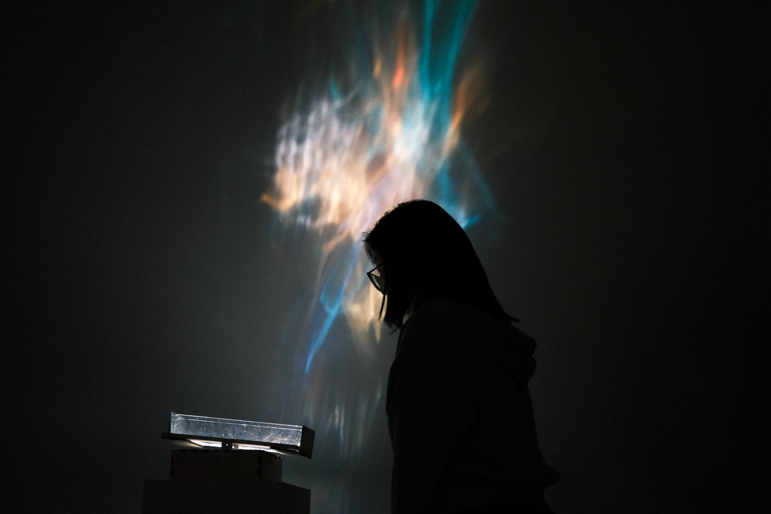
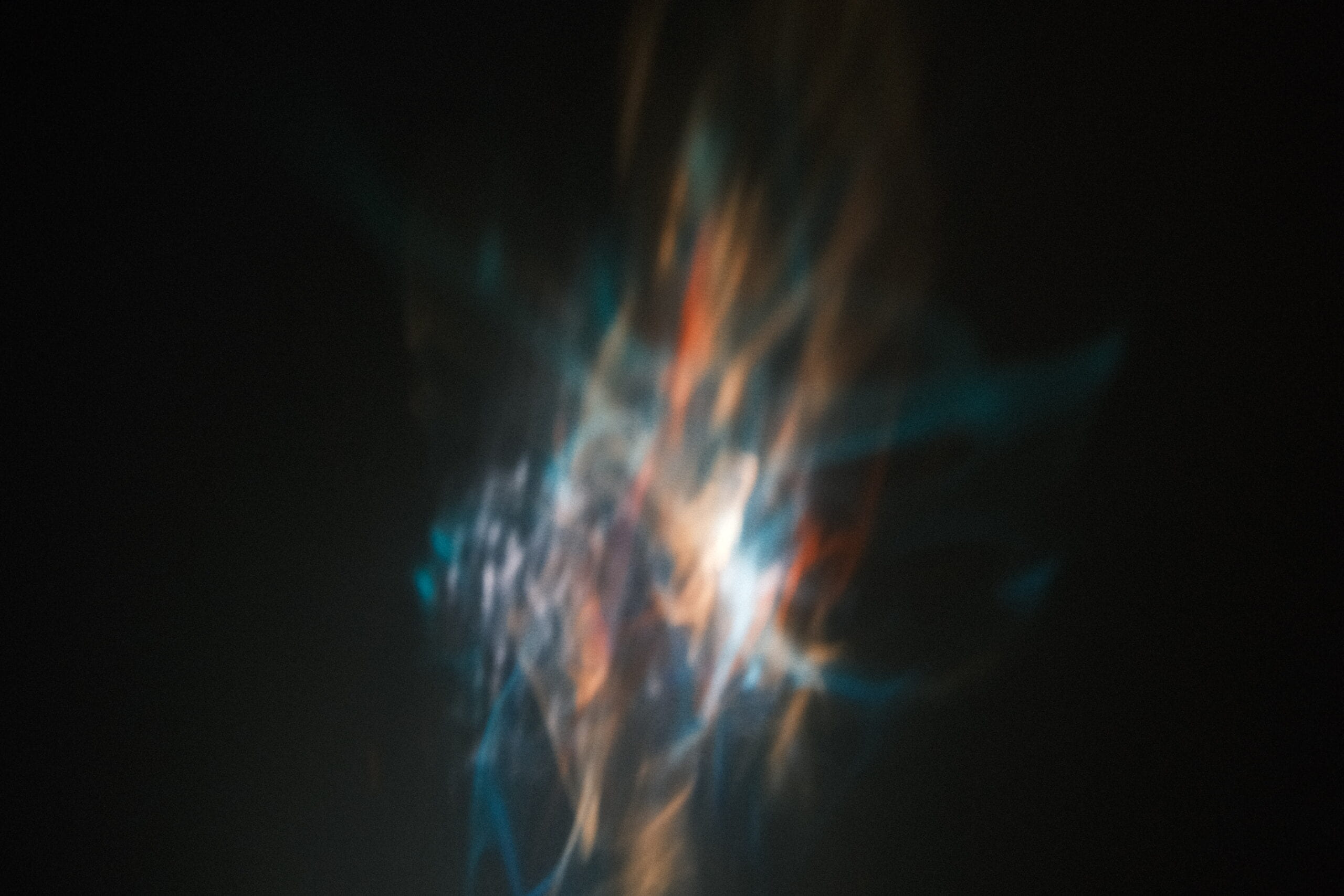
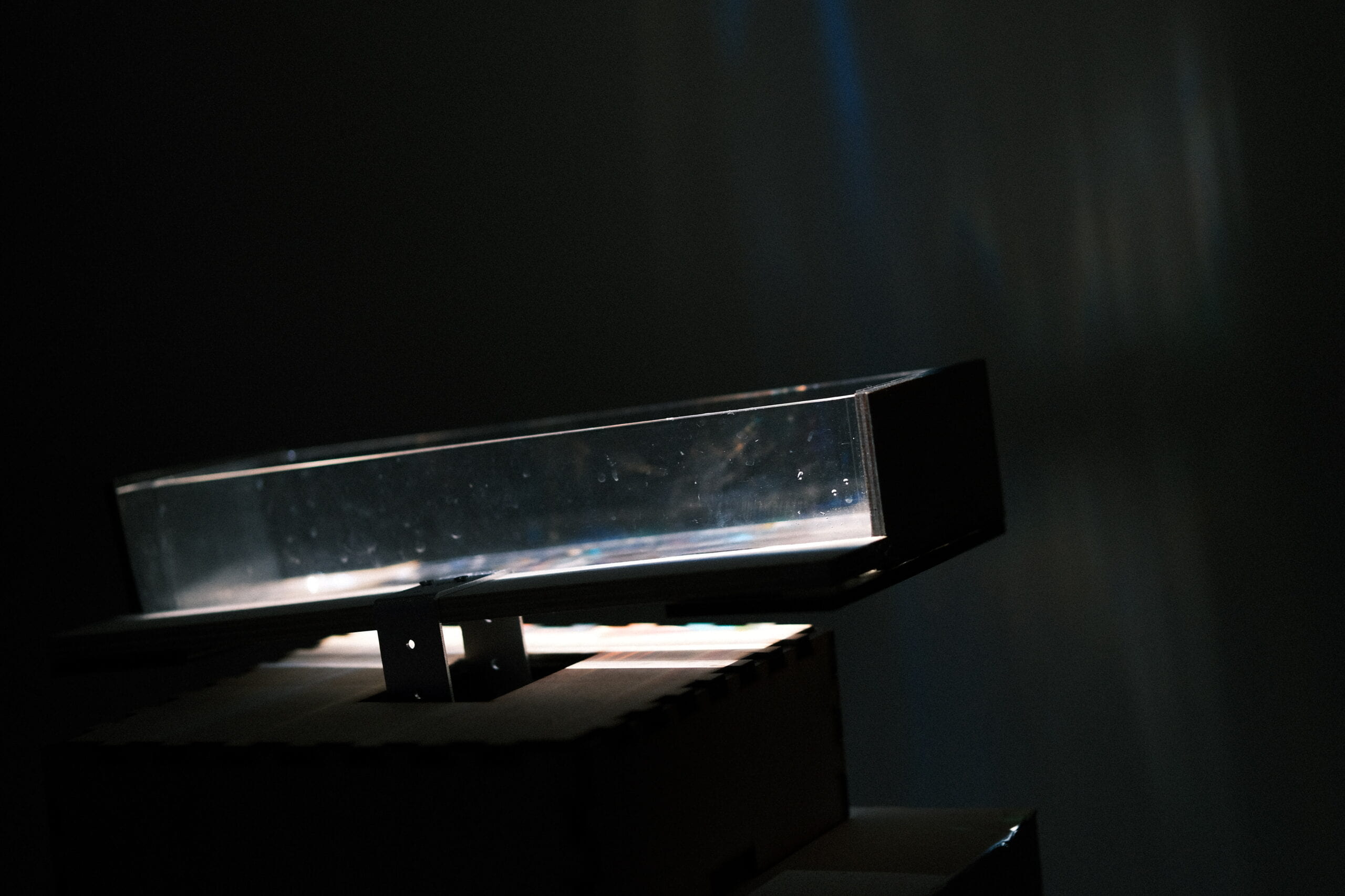
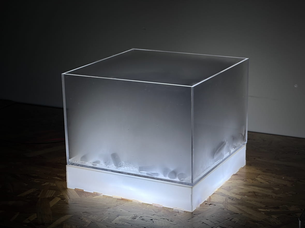
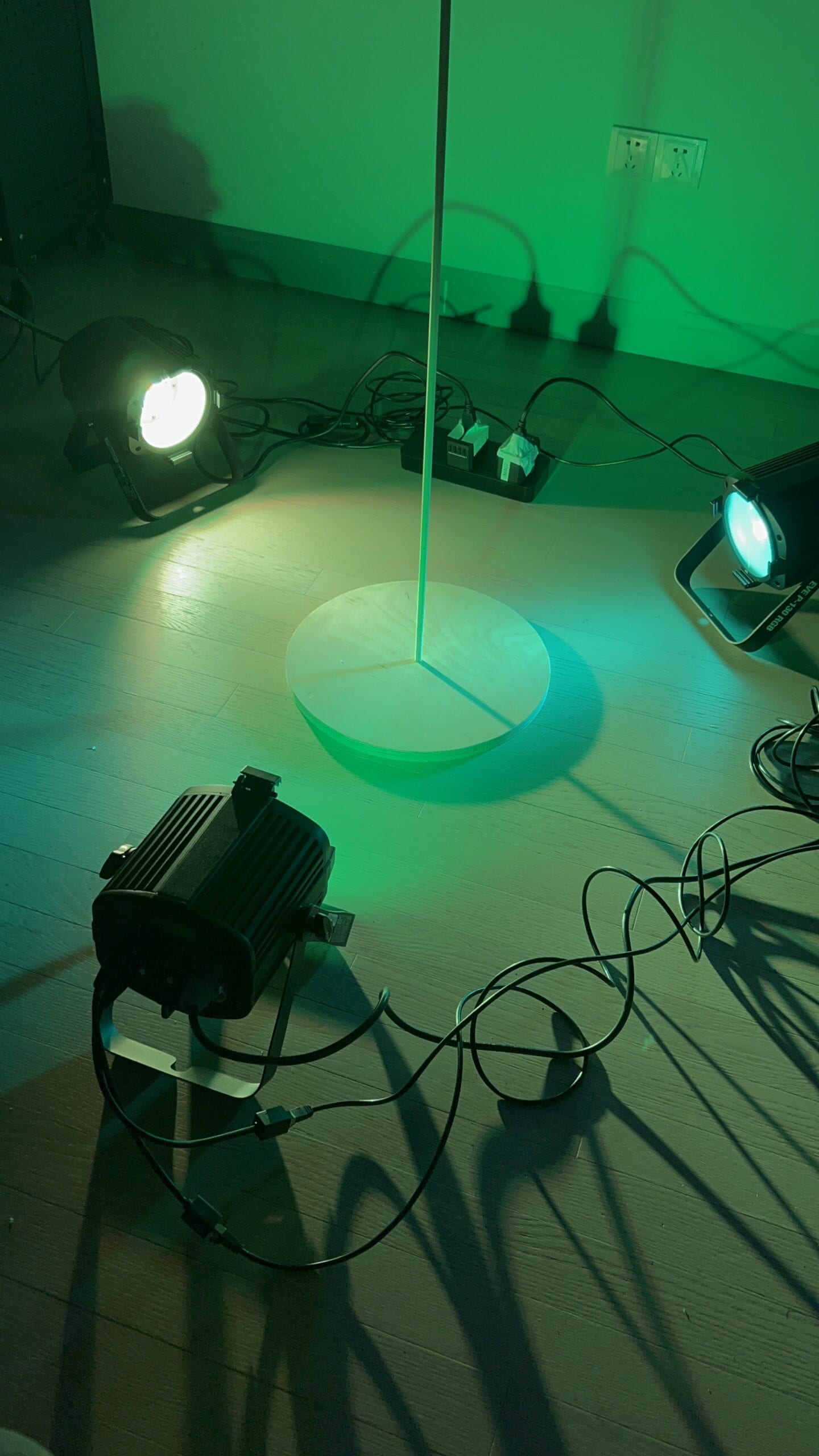
This project is kinetic light sculpture that projects dynamic light on the wall by using servos, water and refractive plastic. 

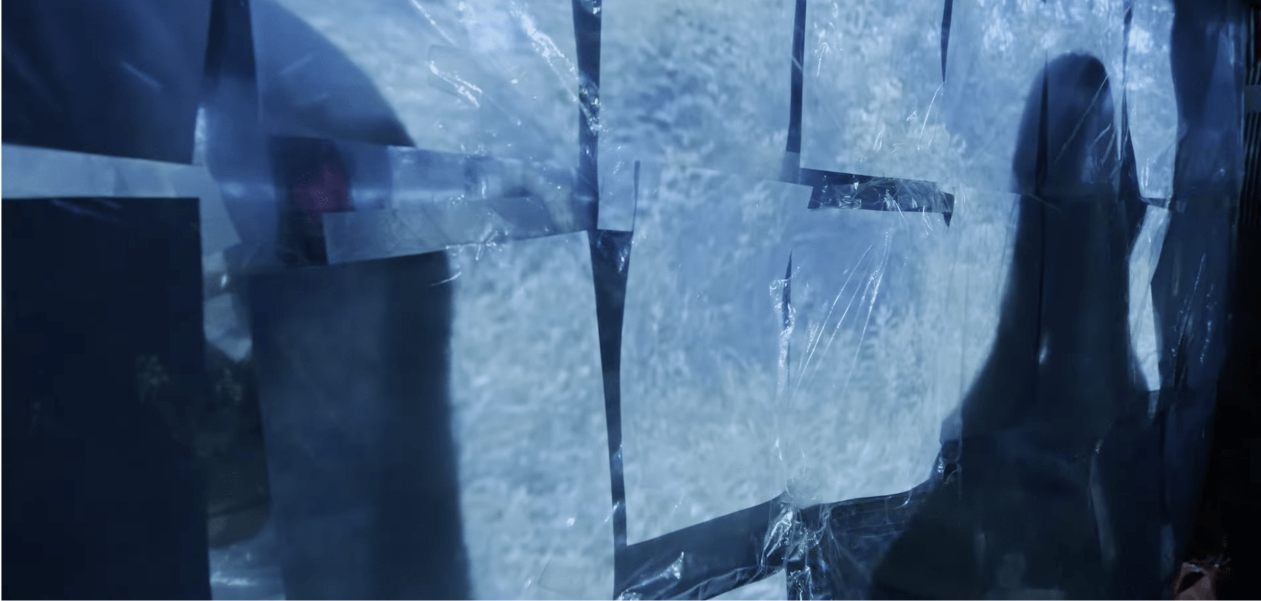
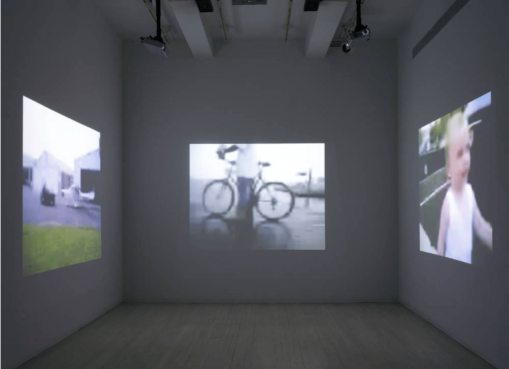
I got the inspiration for this piece during midterm while I was trying to reorganize my saved videos folders on bilibili, and I came across this video (which I’ve long forgotten about) that showcased some art installations related to light. And the piece really struck me as gorgeous. But I did not continue to develop on this in midterm because I did not know how to make the floating material wobble in the container like in the video. And after covering mechanisms and motors in the second half of the semester, I feel like I could give the idea a try.

Here’s a video of the final version of the project:


Perspective and Context

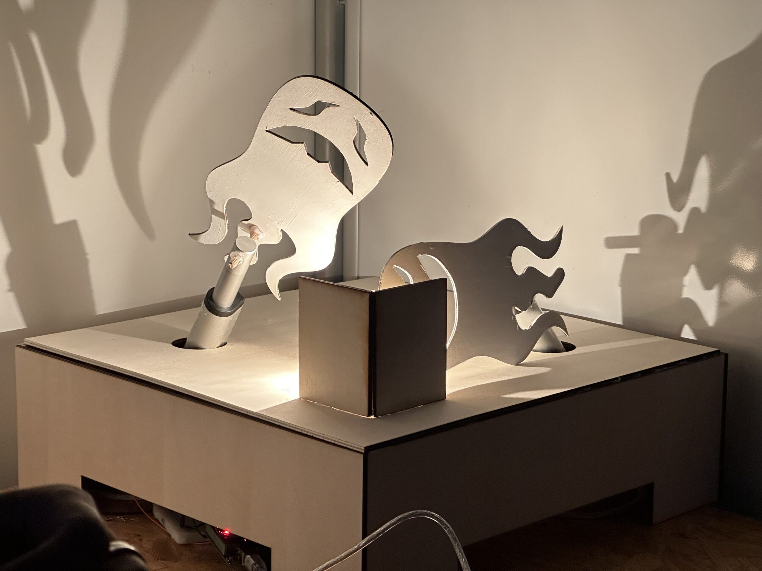
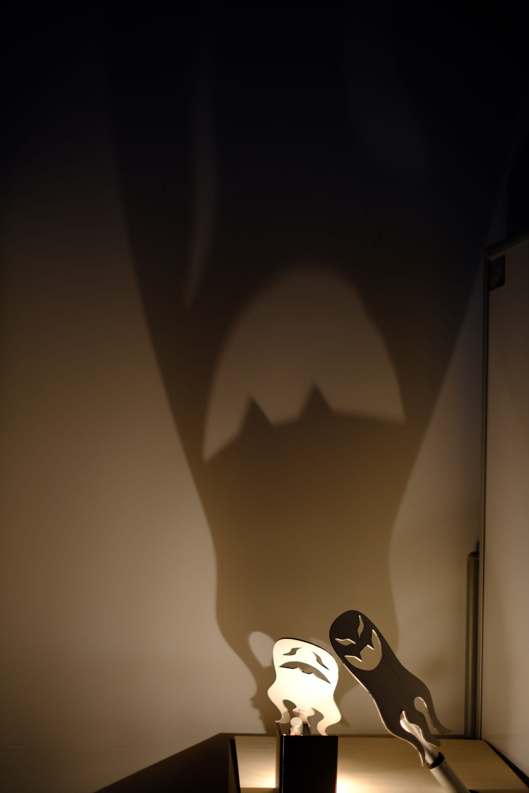
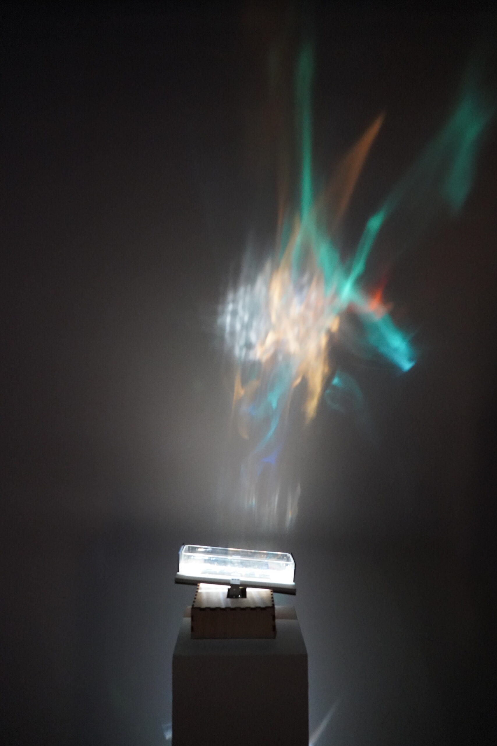
What I really love about this project is that it creates something that takes up quite some space with very little physical fabrication, and the rest of it all depends on the light. And with a repetitive motion with two servos underneath it, there’s also a sense of industrial/mechanical vibe to it, that in some way contrasts with the refraction that was projected onto the wall because despite the whole thing being “manufactured” intentionally, the shapes and movement of the animate light looks very soft, blurred, random, as if created naturally. The repetitive motion also gives it a sense of calmness to it, because the degree it was tilting back and forth is relatively small and constrained in speed, especially combined with the elegant refractions, so the whole piece looks like an innocent creature of an mechanical world that minding its own business, doing its own thing, while unconsciously radiating charm. I was also very happy with the amount of the motion it has, that it is moving enough so people would be sure to notice, but that it won’t distract too much attention that anyone would miss what’s happening on the wall behind it.

Development & Technical Implementation

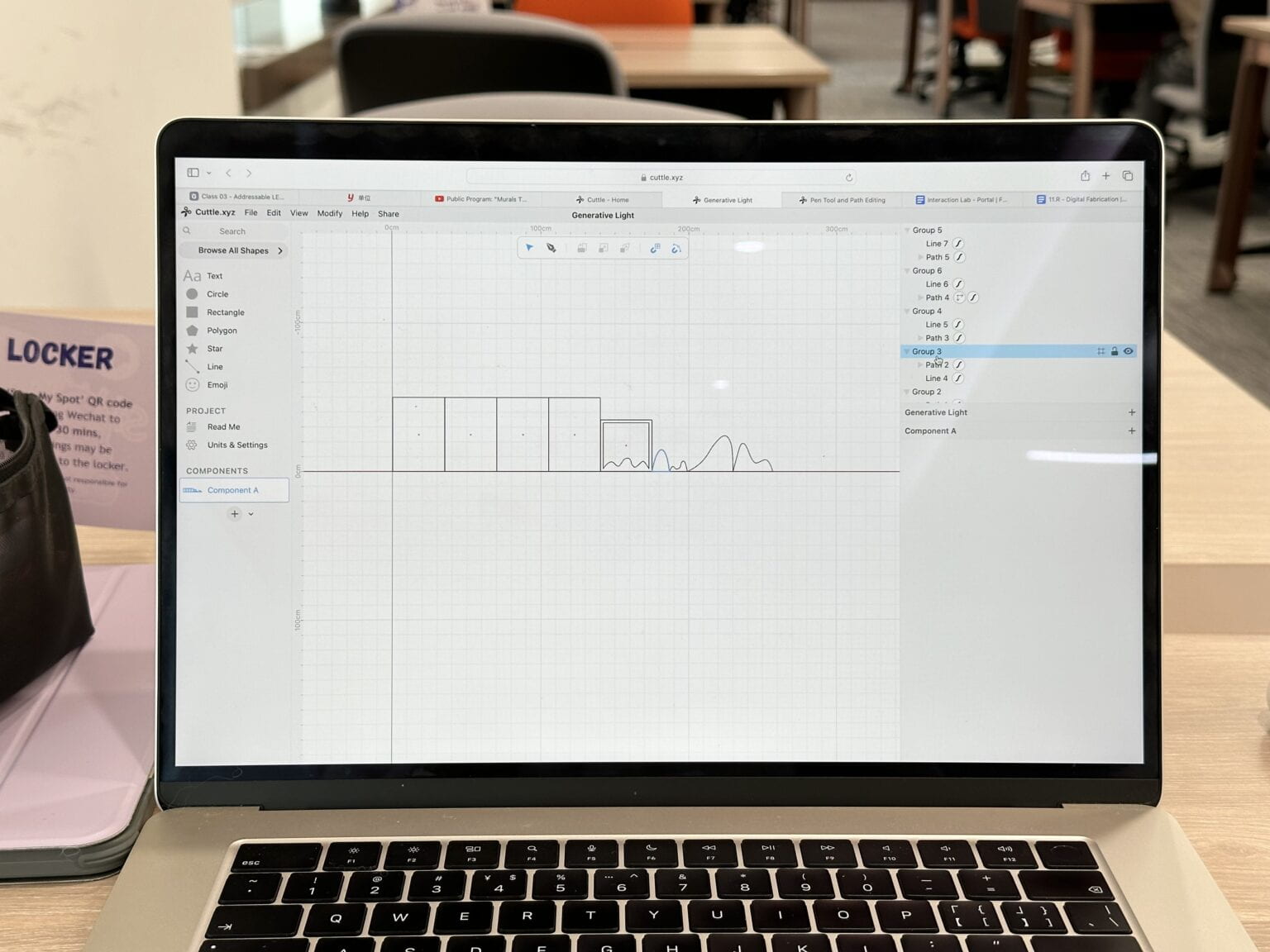
Container & refractive plastic

I really wanted to figure out how the magnificent reflection on the wall was achieved, so I started to look for materials that might be or close to what is shown in the video

I had a hard time figuring out how the magnificent reflection on the wall was achieved in the video and looking for materials that are suitable for creating something similar to it.

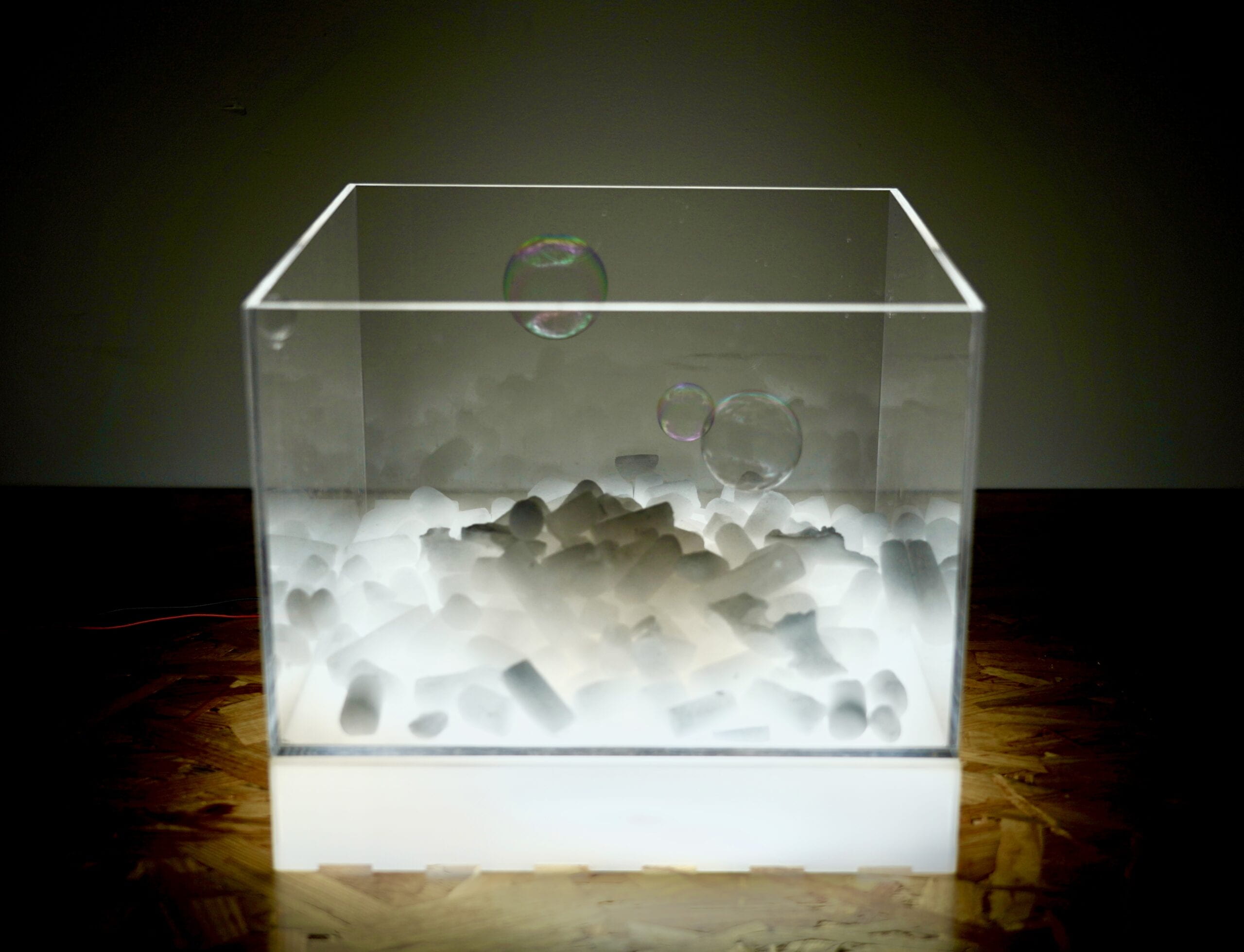
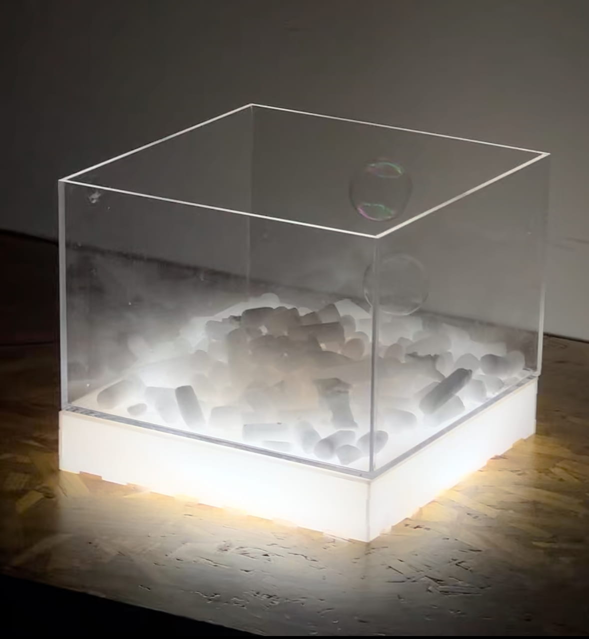
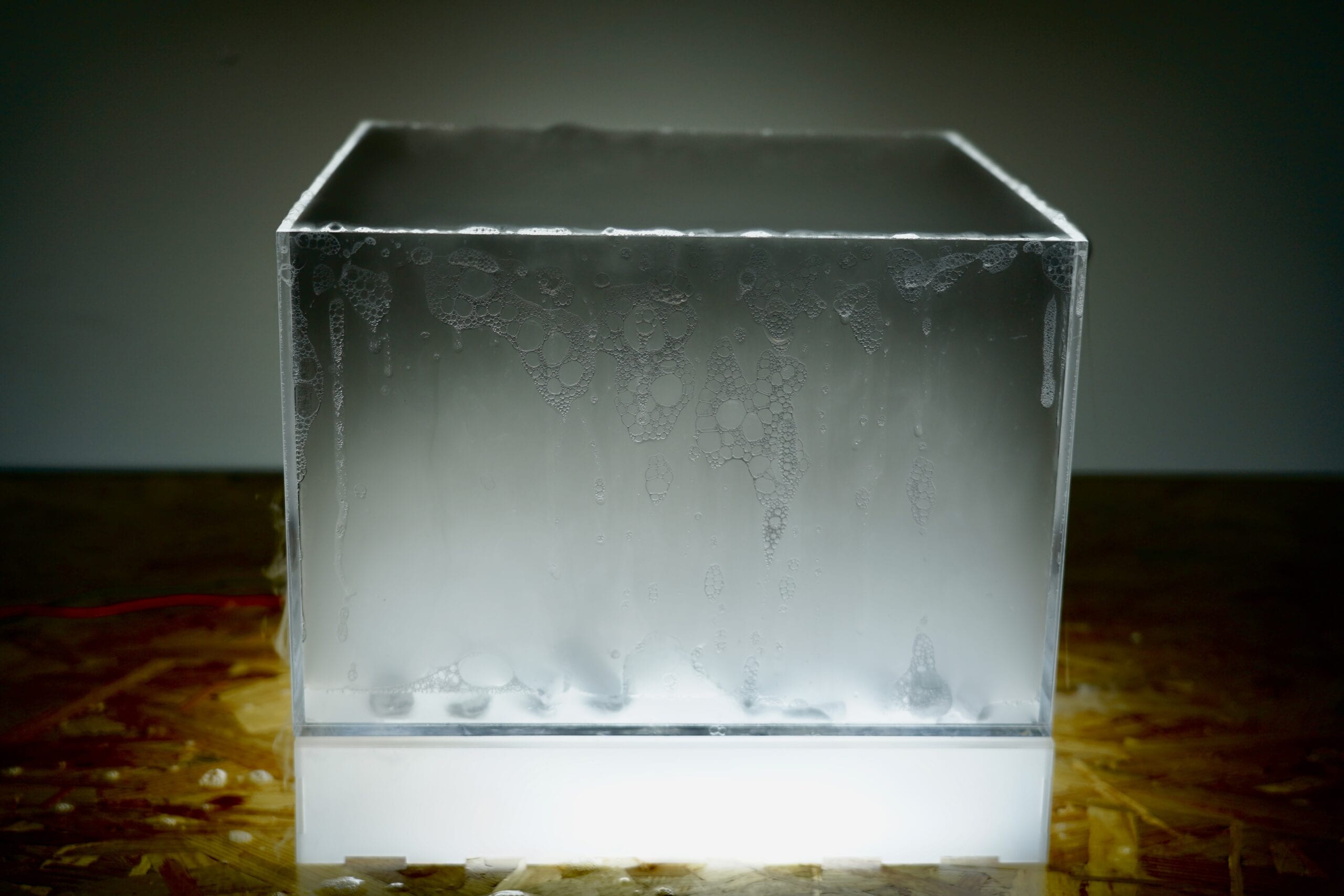
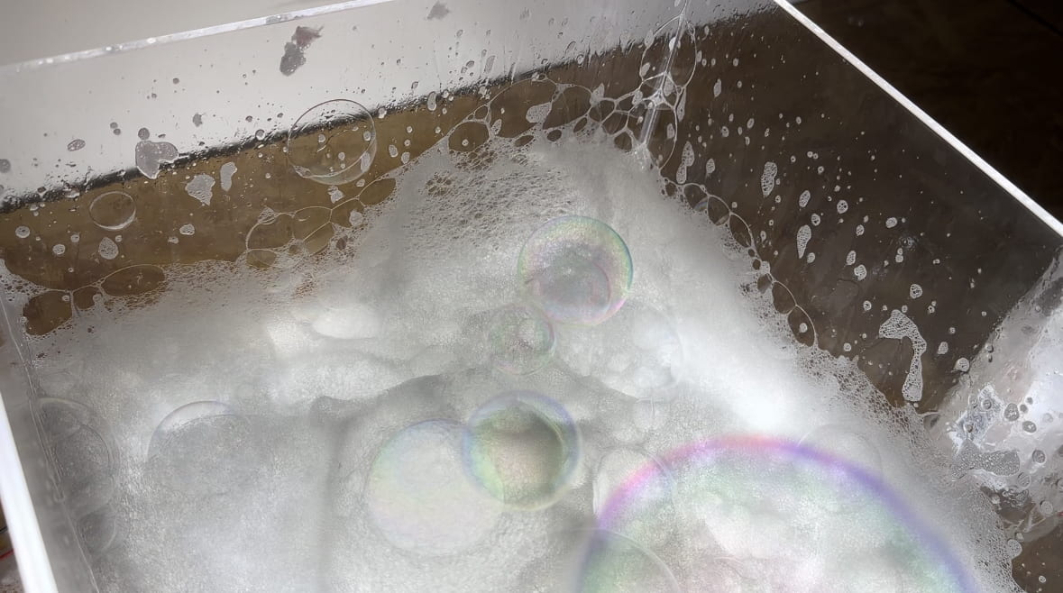
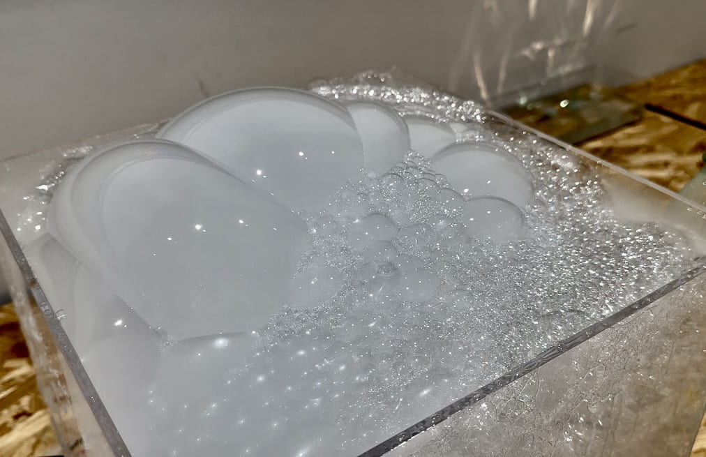
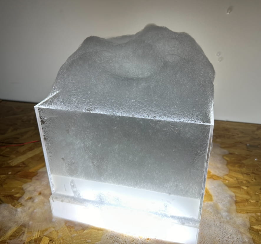
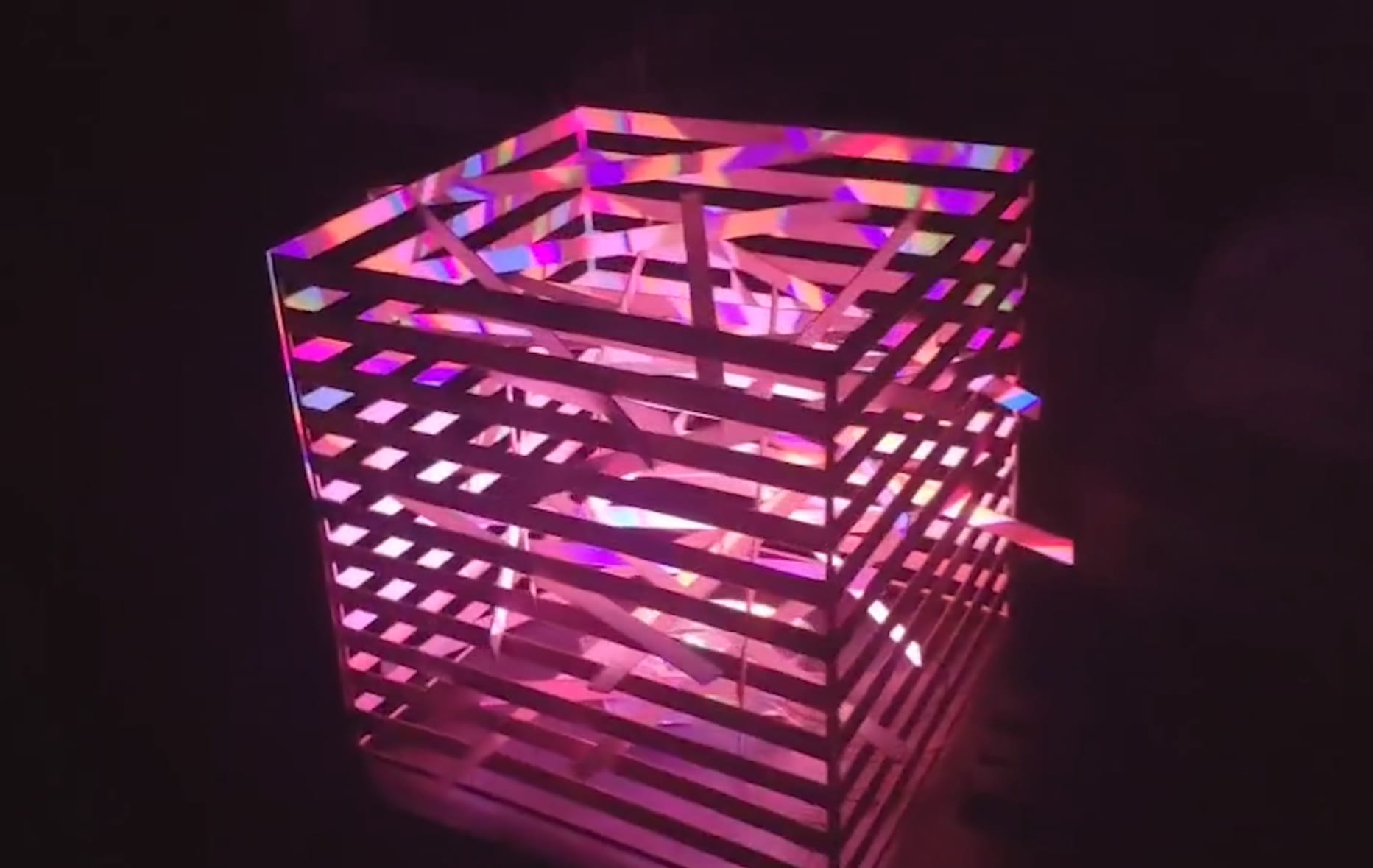
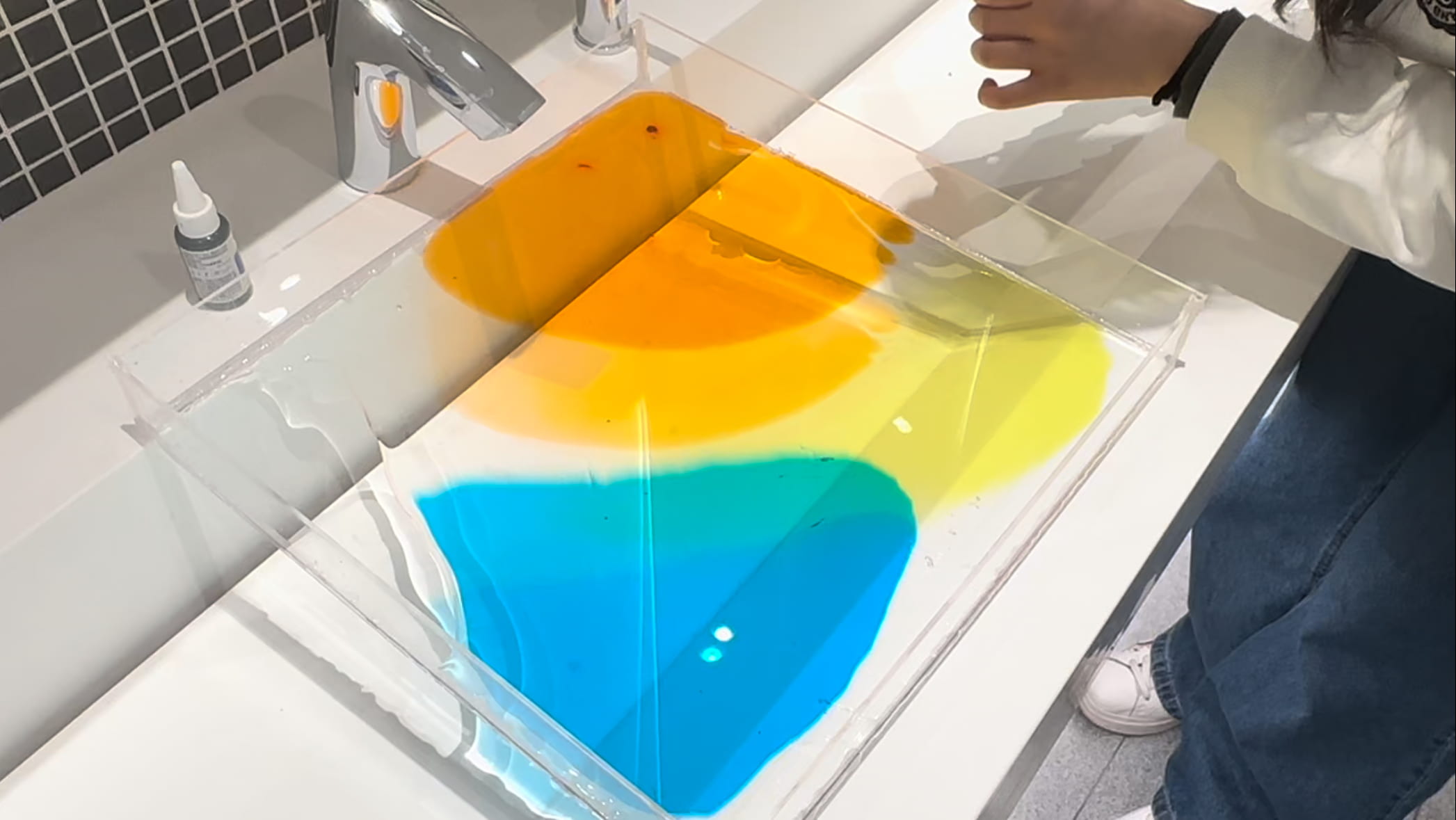
First was the material that creates the refraction. At first I thought those were really thin layers of prism glass, but after searching online, I realized it is impossible to have a prism be shaped like a thin layer of glass and it is impossible to have it float on water. So I substituted the material with some colored refractive plastic and tried it out. Though the effect was very different from that in the video, still they looked very pretty, so I kept it for the project.

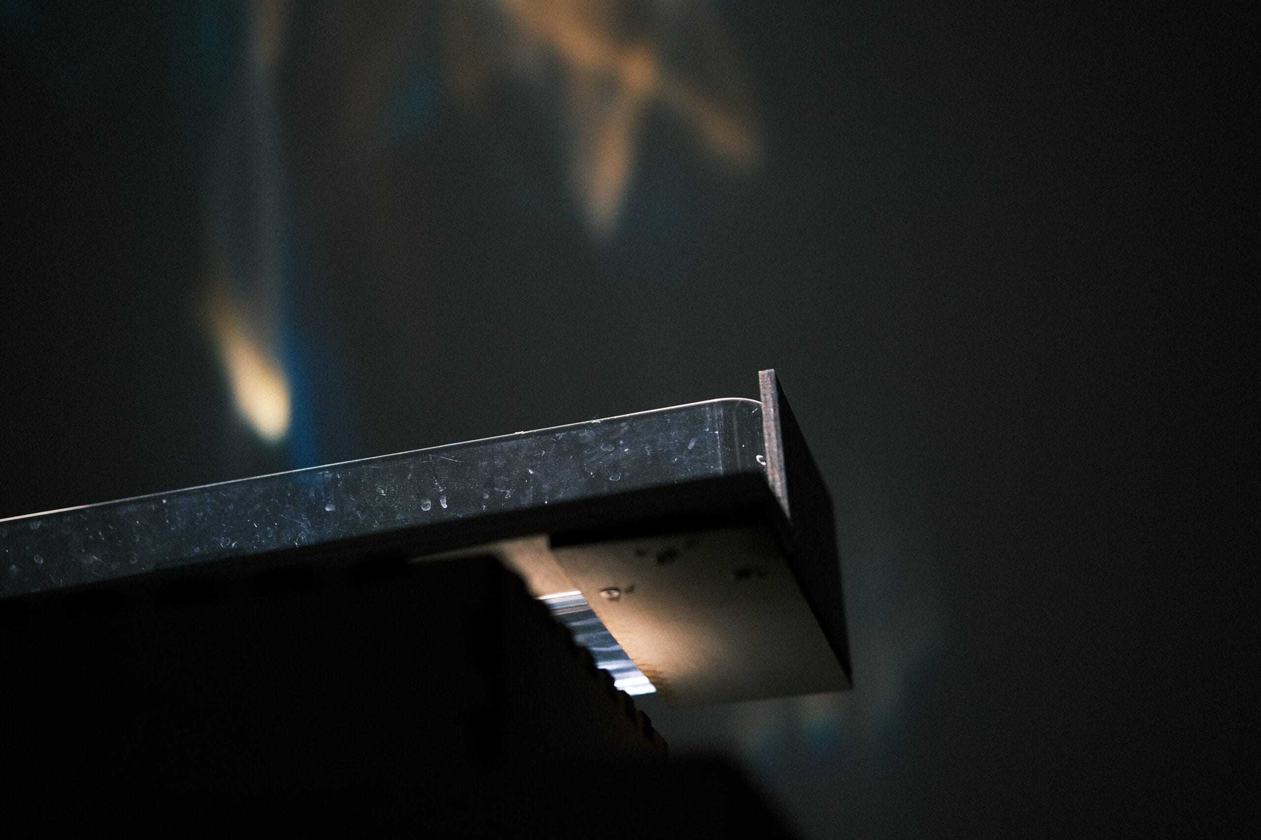
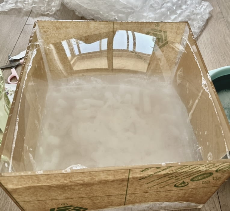
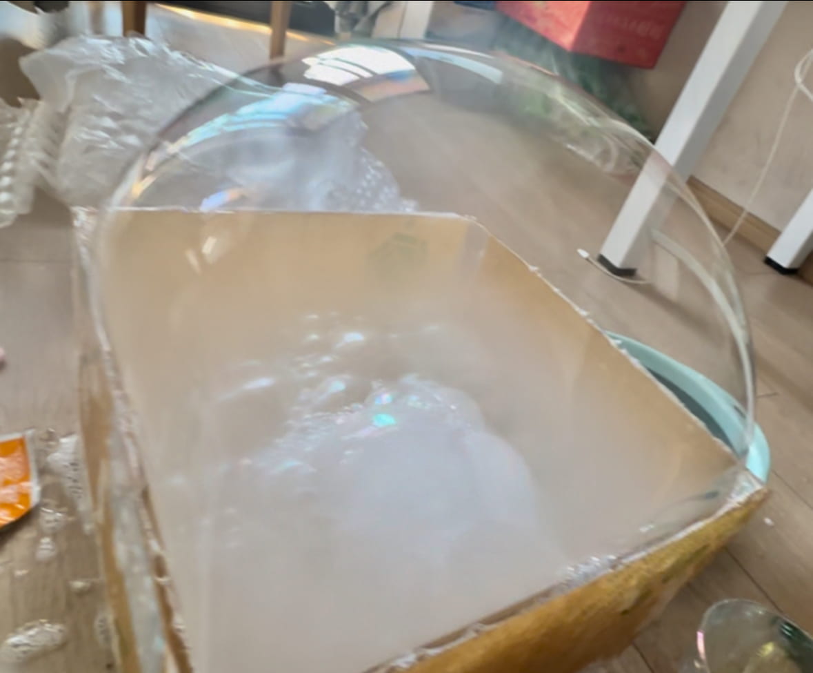
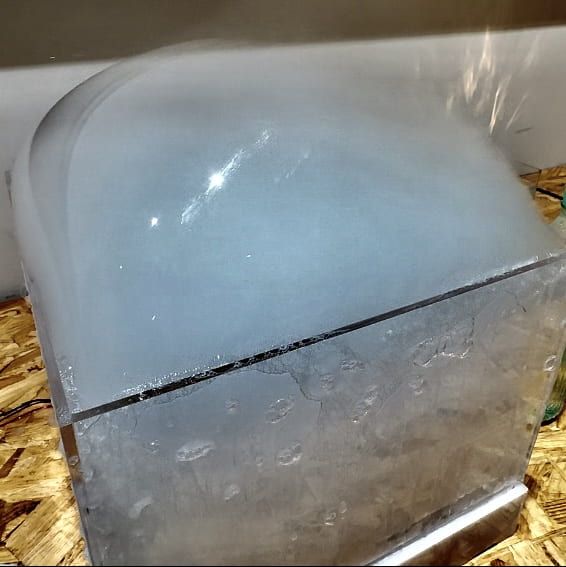
Then, I needed to get a watertight but lightweight, have depth but not too deep, long in length but short in width, see-through container. How hard could it be? These acrylic boxes are see-through, but it’s too thick if it’s watertight, and hence too heavy; This box is long enough in length, but too long for width; this box’s length and width are perfect, but way too big in depth, and that one’s too shallow that the water will definitely spill; this one this great, but why does it have holes on the sides… You might ask: why don’t you just laser cut your own box that meets your needs? Well, from what I learned from my midterm, it is almost impossible to hand-stick a watertight box no matter how much glue you use. Just when I was about to give up, I saw this storage tray that its sides are connected with cambered surfaces, which means it’s almost a plastic bucket that looks like a box, and it has the size and shape catering to my needs, and it’s very cheap. (Had I seen this coming I would’ve searched “plastic storage tray” instead of “acrylic box”.)

Servo & servo mount

Like I said, I had no idea how the servo would support the container, but after I’ve realized that I need two servos to do the work (thank you Eric for the suggestion), making the servos move synchronously based on how they are installed became the more difficult issue. It was very confusing, because to figure out how the servos would move, I needed to know how they are situated relative to each other. To figure out how they should be situated, I need to mount them on servos mounts (thank you Eric again for the suggestion). But when someone who knows nothing about them sees pictures of various mounts, the ability to picture them installed together with the servos moving was near zero. So I looked through the pictures of people’s finished work using the mounters posted in the comments and tried my best to figure out which type of mount I should buy. 

The first round of purchase, I got what is suitable for installing the servos themselves so that they are stable enough to support weight while working. I initially intended to just drill the two onto each side of a wooden stick, but then quickly realized that the premise of doing so is that the positions on both sides are exactly the same, and the starting and ending positions of the two also need to be the same. The slightest difference would prevent it from working. So I then had to look for a way that connects the two servos (thank you Eric again for the suggestion). 

But isn’t that basically the same as drilling a hole on two sides of a stick? It took me probably an hour to think of a solution: buy another servo mount. I know it sounds stupid but the mounts do look very different as I recalled that there was a U-shaped mount that might do the job, and did a second round of purchase. Luckily, it worked very well with the small piece of wooden board I snatched from the wood fabrication room, and all that I needed to do next is to drill the board onto the U-shaped mount. What could go wrong?
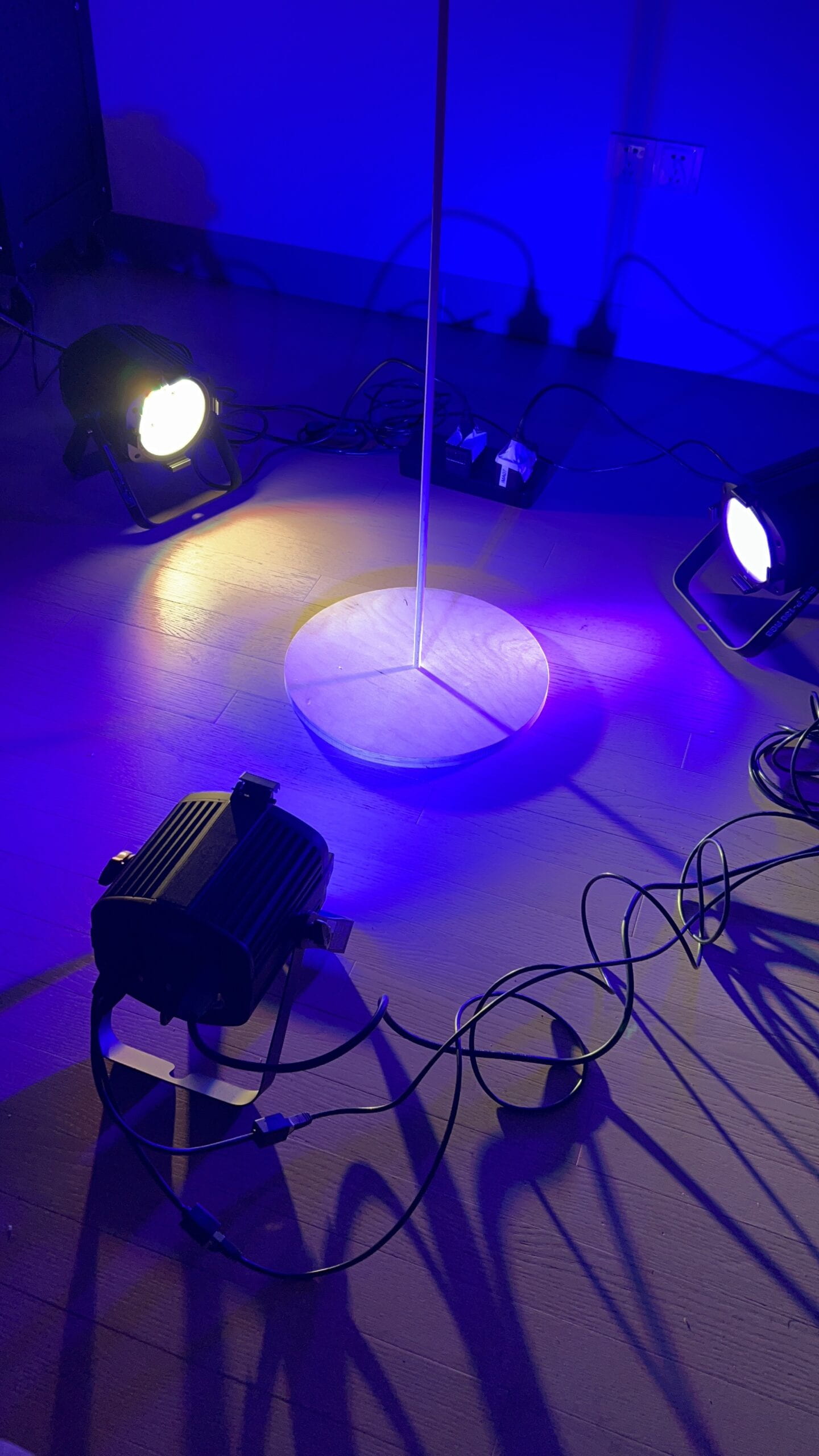
Base & support

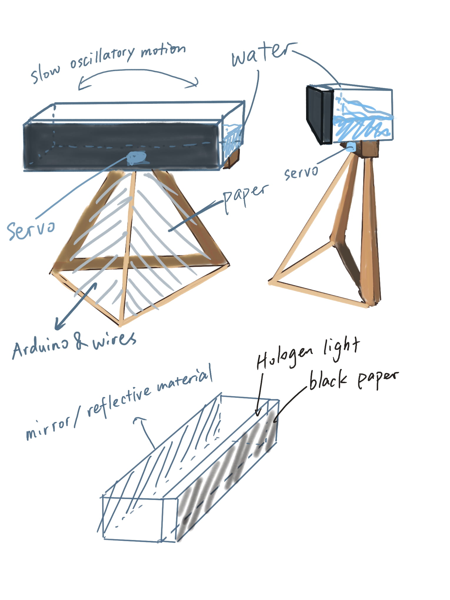
As you could tell from the sketch I drew for the proposal the base does not look like an actual finished piece. When I was still in my “daydream” stage, I figured it would be nice to have the base also act like a pedestal, so the projection would be ideally around or slightly above eye level. But after I’ve settled with how the servos should be installed (which is basically built for putting on a flat surface), making a box around the servos became a much more reasonable and easier option. 

I made a lidless box, cut a square hole on the bottom and flipped it upside down. The tricky thing about this is the measures of the box. It needs to be high enough to cover up the servos, but not too high that it prevents the wooden board that supports the container from moving side to side. Same issue with the size of the box, but it also needs to be big enough that it fits the Arduino and the breadboard. After a series of careful measurements, it still ended up being a bit too deep, so I attached another 9mm thick wooden board underneath the two servos, and changed the U-shaped mount to a longer one. 

Because I wanted the container to be as close to the wall as possible, having it right on top of the piece of wood that is above the center of the base box would then let the box underneath get in the way. So I drilled two more boards on each side sticking out in the same direction to support the container, and glue gunned another two pieces of wood horizontally to prevent the container from slipping off while rocking from side to side. 

Servo & Code

I thought if I situate the two opposite servos in a certain way they will be moving in the same direction while running on the same code. Turns out they can’t. So for the other servo I changed it to 340 minus the other’s agree and worked. (For some reason it only works when it’s 340 instead of 360.) At this point I’ve had the servos moving like a small seesaw. But I noticed that the speed of the tilting left and tilting right are not equal, with always slowing tilting to one side and quickly to the other. I couldn’t figure out why it was behaving like that. I tried to do some adjustments, but very unfortunately burned my Arduino when reconnecting the wires. I then tried other types of Arduinos and eventually the same ones but they all make the servos behave very differently despite running on the same code, and it is impossible to make them turn in opposite directions. 

Because I was testing with a code that previously worked, I had no idea how to modify it. So I dived into this cycle of changing all the possible variables in different combinations and see how the servos reacted. Maybe I got lucky, because the day before the IMA show, with the Arduino that Eric borrowed me (thank you Eric!), I got the movement I wanted.
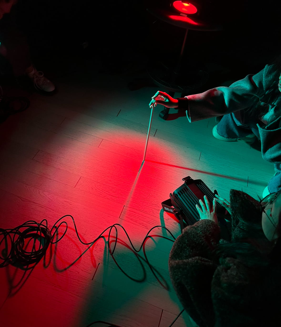
Light


As seen in my sketchy testing video above, the light source needed to be emitted from above the container rather than below or anywhere close to it in general. But because I was having my focus on the servos, I did not take a lot of consideration into the light and assume that having a halogen light sticking out from the bottom of the container, similar to how I envisioned in the sketch for the proposal, would work.

I bought some hard black cardboards and mirror paper in hopes to concentrate all the lights, seal them inside the container, and block the bright light of the halogen bulb from the viewer. 

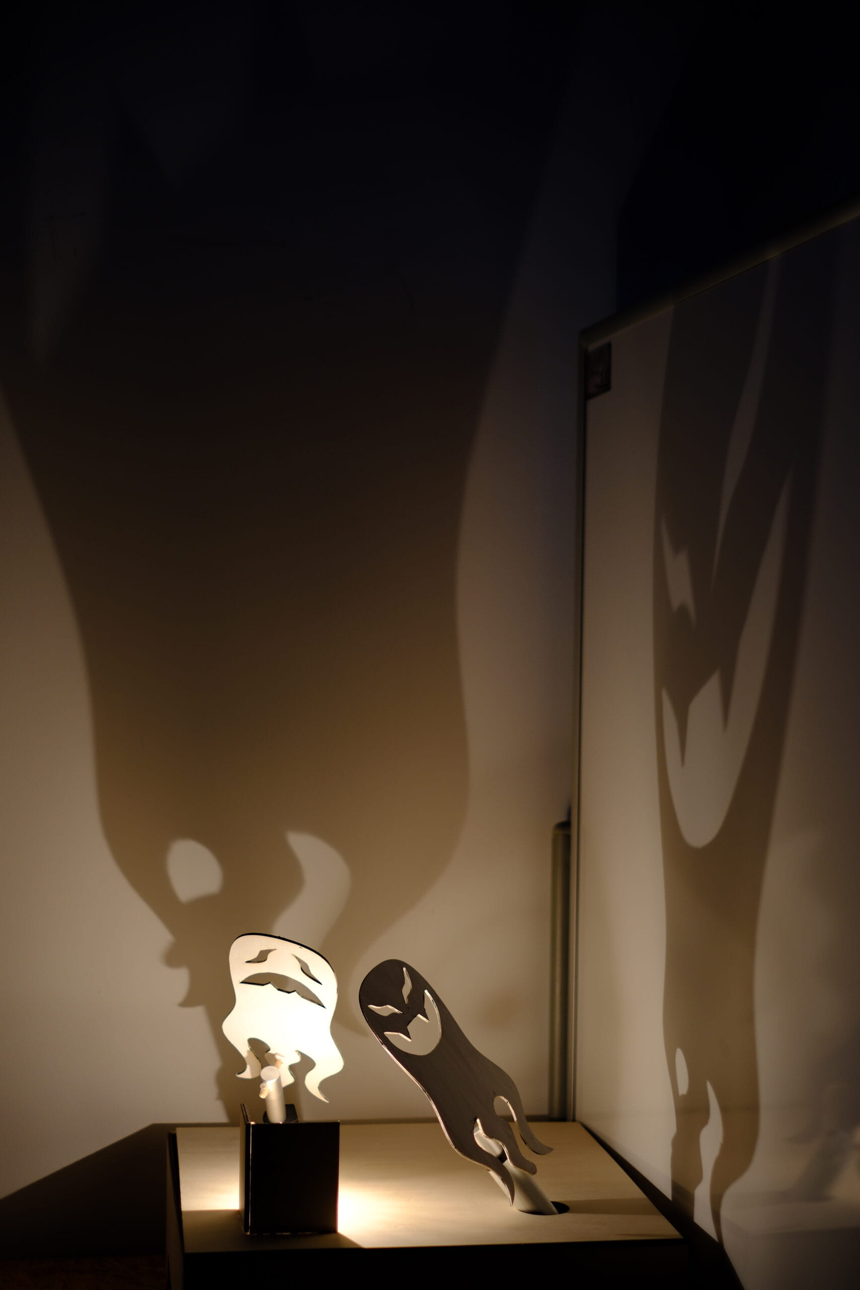
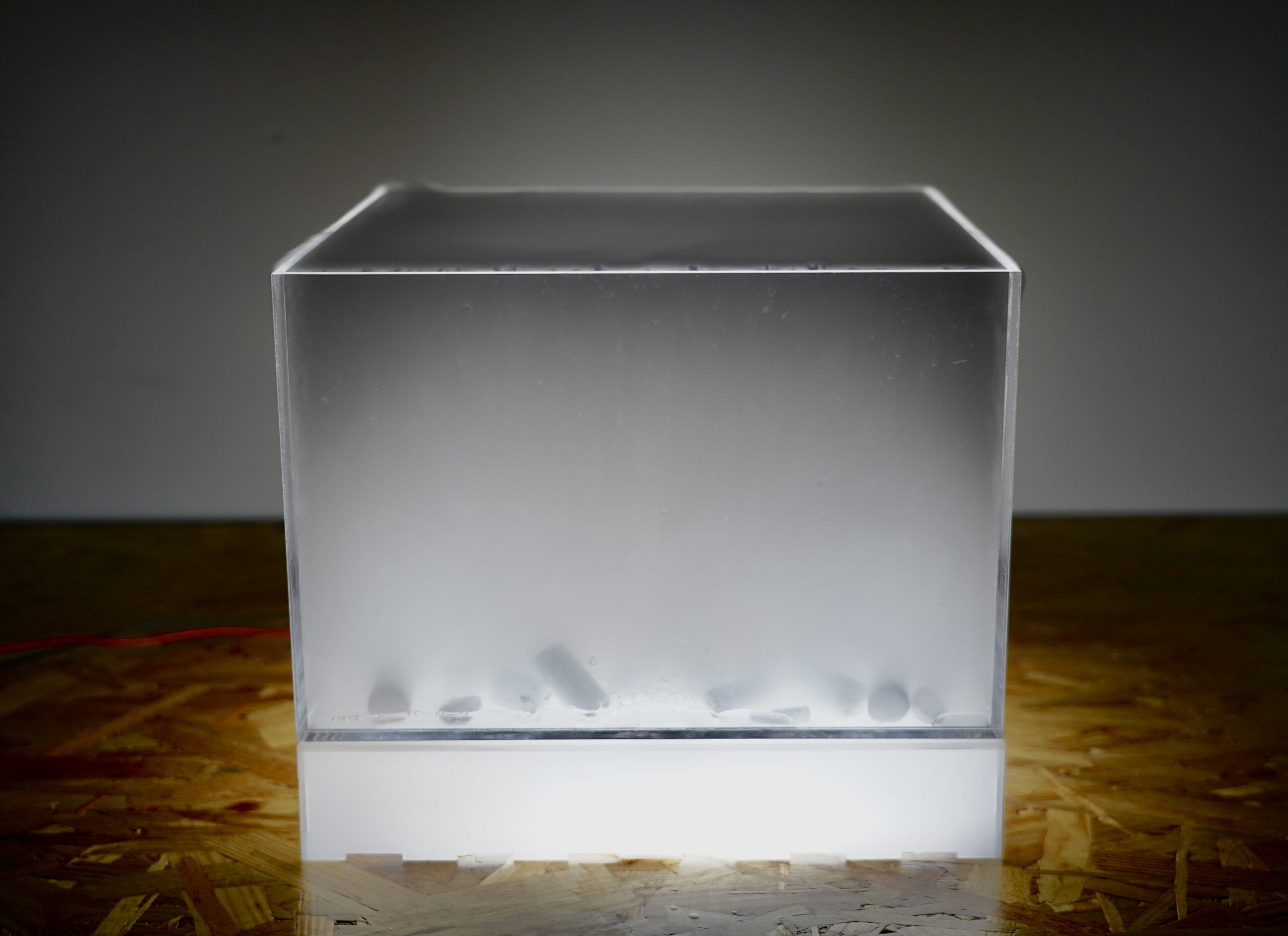
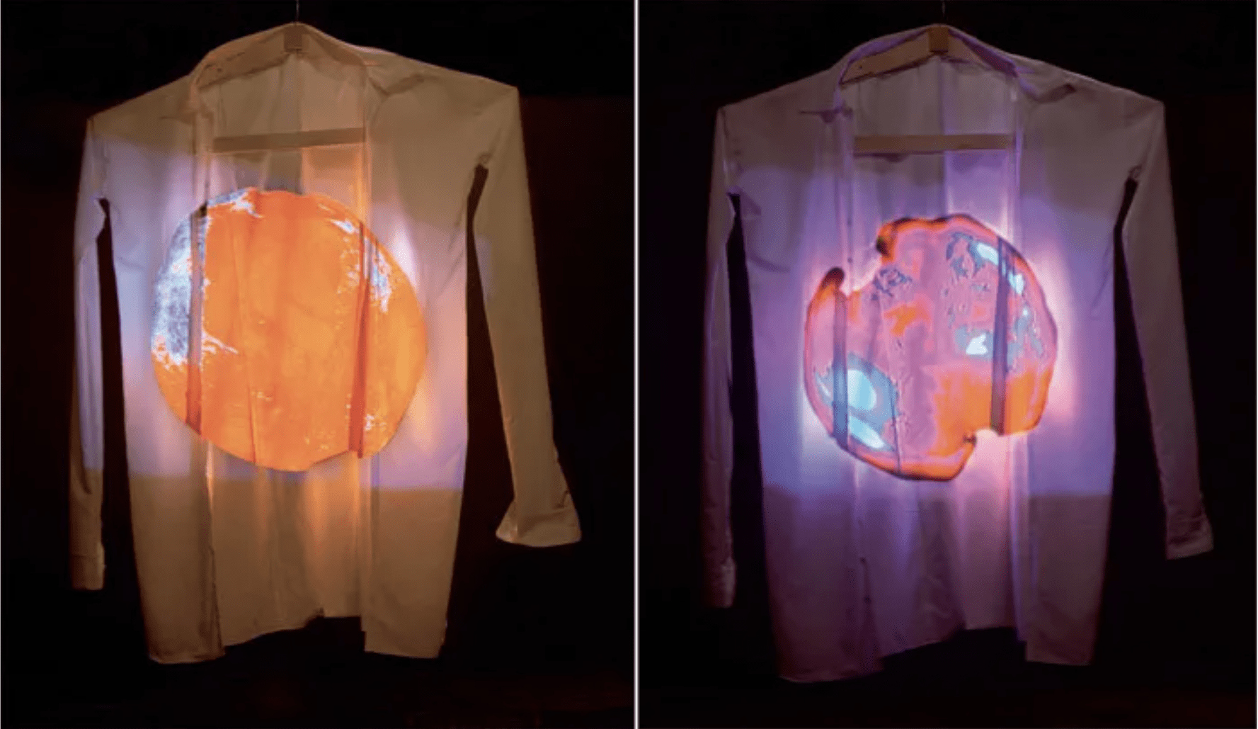
It was not until a day or two before the presentation that I tested the light (which I regret doing that late), and the effect was not very satisfying. The projection on the wall was a lot smaller than I had anticipated and the colors of the refractive plastic are heavily covered by the yellowish glow of the halogen light. I realized there’s barely any refraction of the colored plastic inside the container as it was drowned by the strong glow.

I changed the power supply from 12v to 5v and took out the mirror paper in front and below the container. (And having the mirror paper before the halogen light can easily burn it.) It looked better (and safer),  but still not very ideal. The light is still way too yellow and there’s a hoop-shaped shadow for the glass bulb. 

here’s a video of how it looks like with a halogen light:


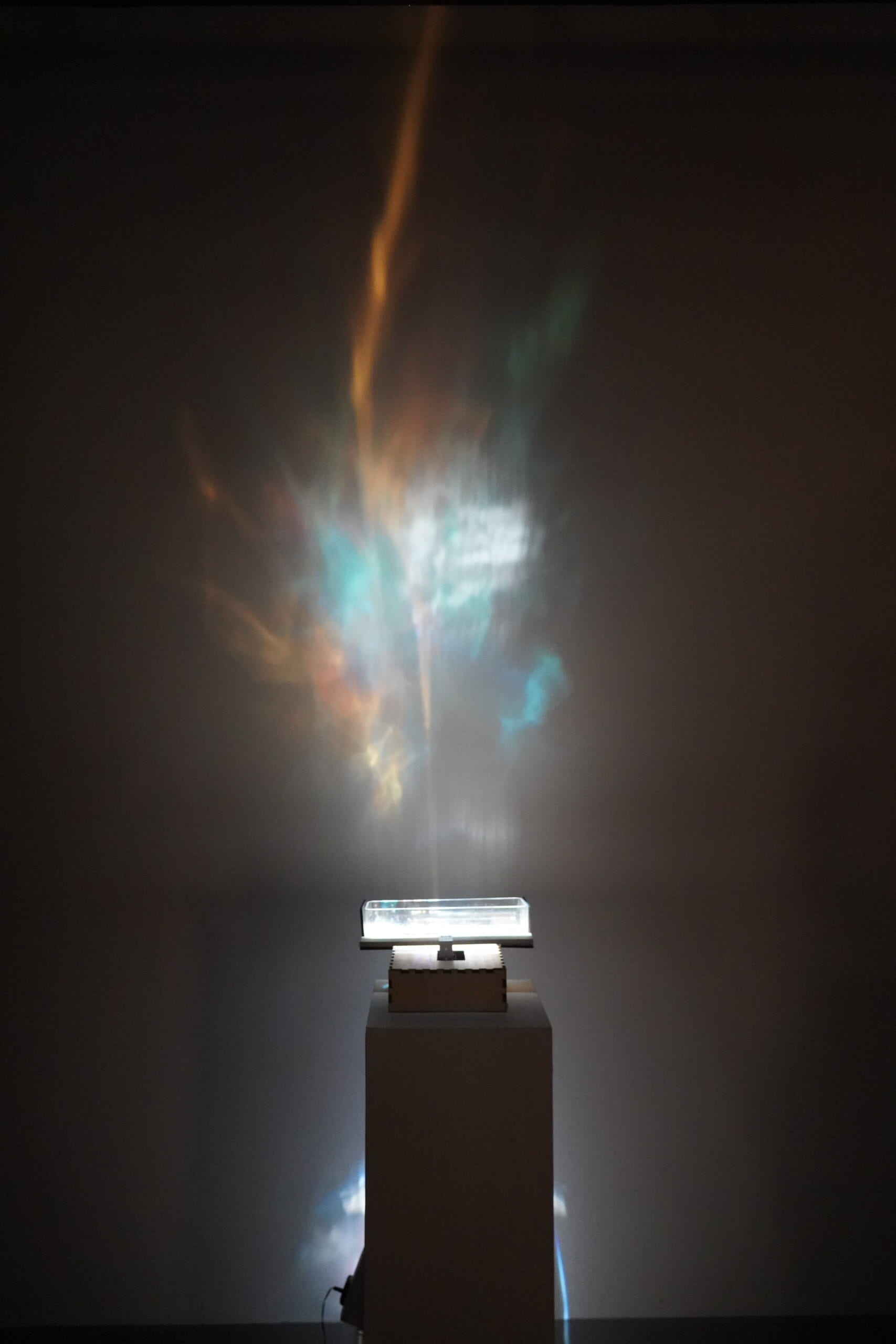
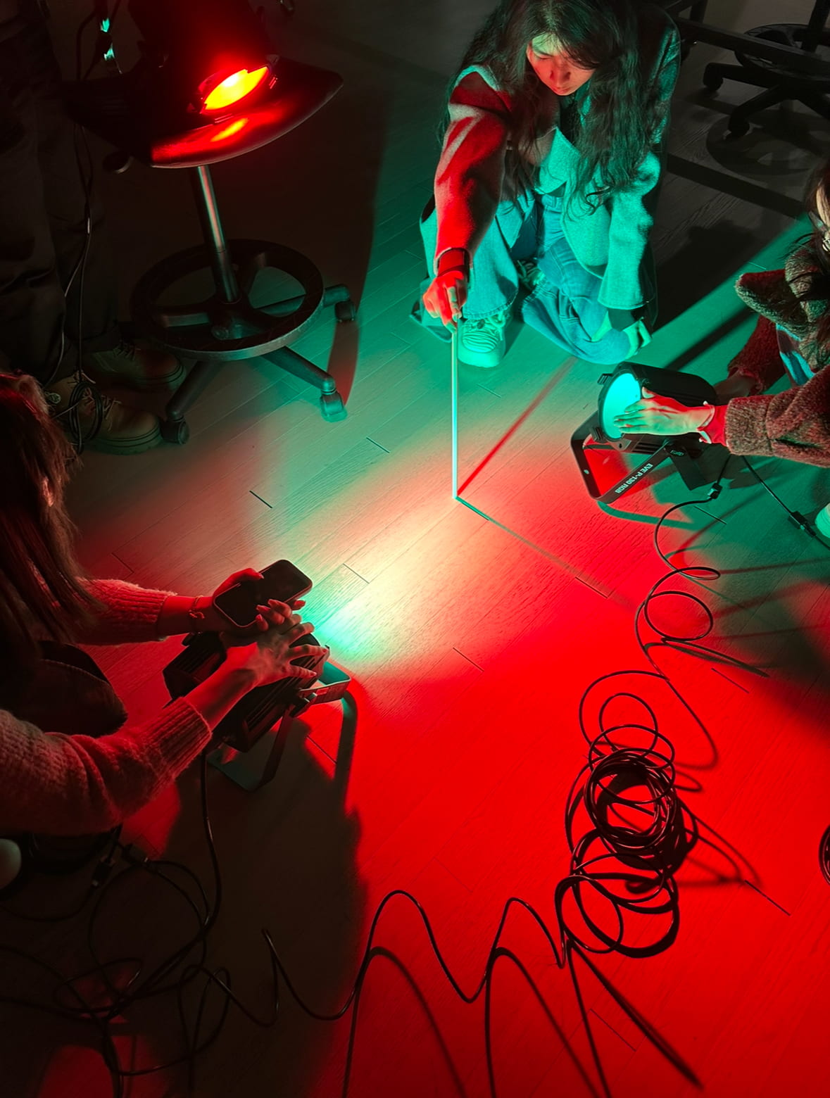
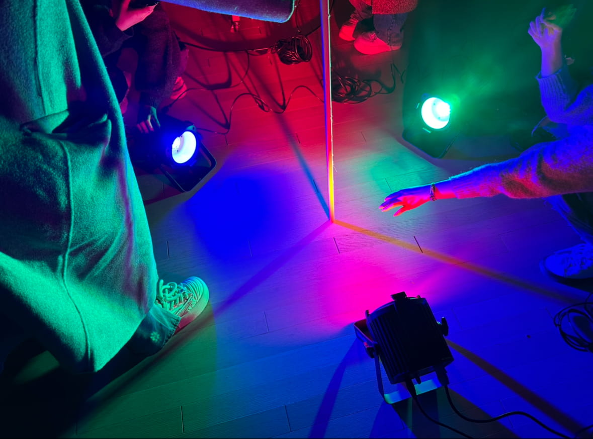
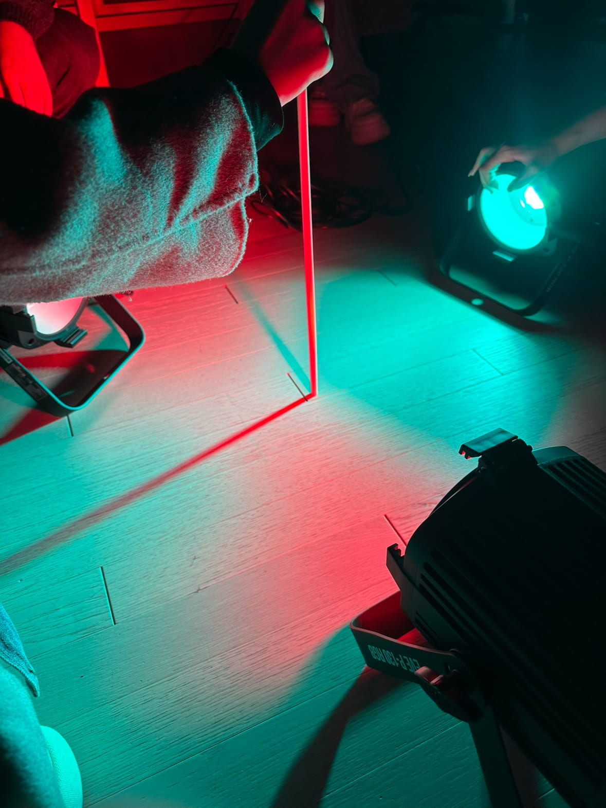
Then Eric came to the rescue with a spot light that had just arrived the day before. I was very lucky, because the spot light made all the difference: the color was cool enough, it beams down from above, it perfectly covers the area of the water surface, and it’s very unnoticeable. Thank you Eric. 

Presentation

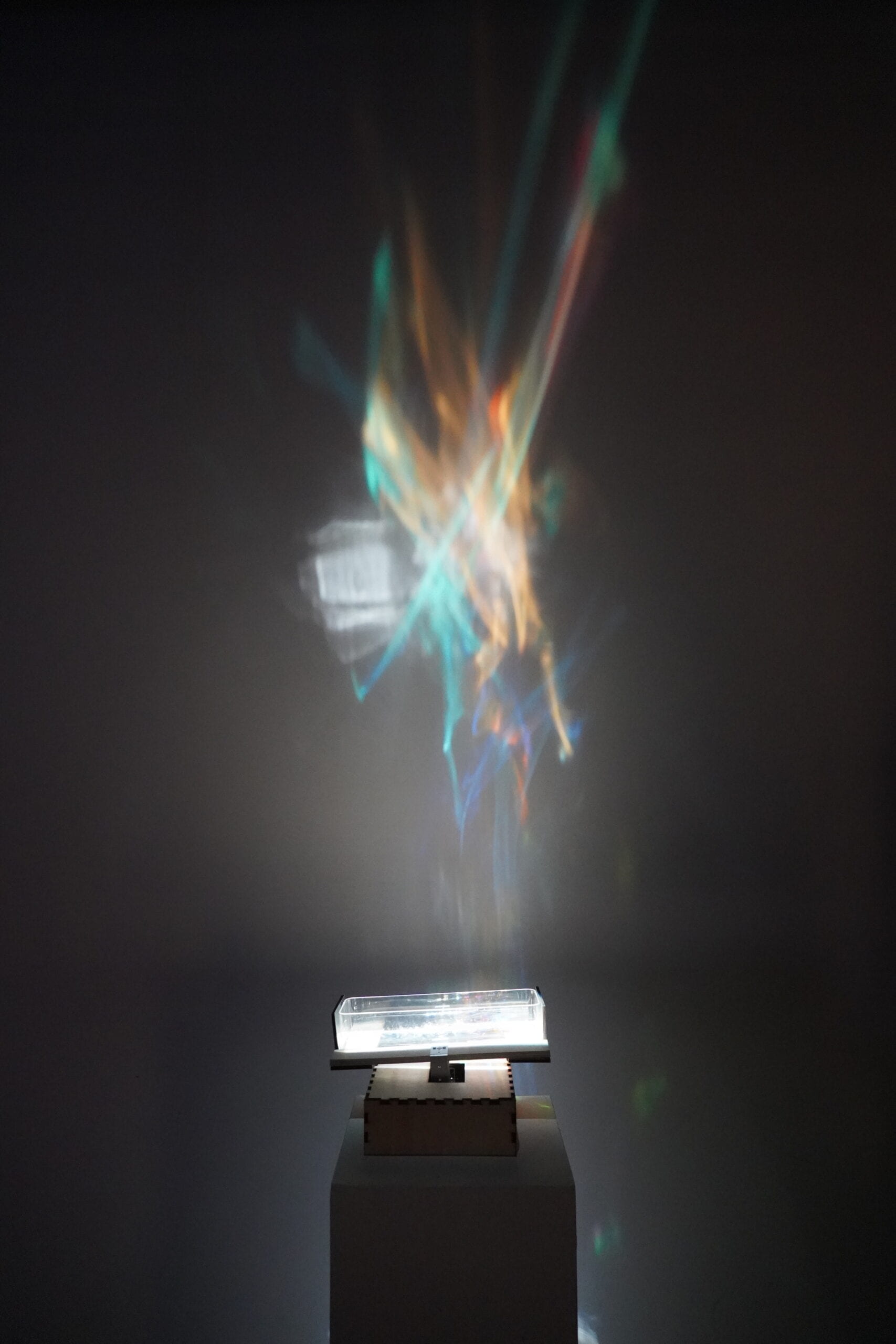
It was really interesting to see people’s reactions with them not knowing it is my project while I’m standing next to them. I was very glad that despite some people’s attention would be first directed to the wiggling container, they would all eventually direct their view upward to the projection on the wall. And all the comments I’ve overheard are positive haha. It was very sweet to hear one professor saying that mine was her favorite piece, and that it was “very calming among the chaos”.

There was a little problem with the colored plastic inside, that after some time a few pieces would get stuck on the wall on one side. I guess it must’ve been uncomfortable to watch when people take a step closer to look at the container. I sometimes would quickly go and scratch them off when no one’s looking but they always end up sticking back on.

Conclusion

I personally really liked the project, but it was a bit frustrating during its process of making because it looks so small and shabby without light that I find it a bit humiliating when people know this is actually my final project. It looks so simple and small that it shouldn’t take more than an hour to make, and I feel very unaccomplished when I see this is all I have after working on it for so long. 

I was thrilled to see that it worked very well in the end, but that is also because I got very lucky, that I had a working light at the very last minute. I guess I should think every step thoroughly in an early stage of the project, and do testing of all the components as early as possible because you never know what’s gonna happen or what it might actually turn out to look like.

Code

#include 

Servo servo1;
Servo servo2;

int pos1 = 0;

void setup() {
  servo1.attach(3);
  servo2.attach(4); 
}

void loop() {
  for (pos1 = 160; pos1 <= 180; pos1 += 1) { 
   servo1.write(pos1); 
   servo2.write(180 + pos1); delay(50); } 
for (pos1 = 180; pos1 >= 160; pos1 -= 1) {
   servo1.write(pos1);
   servo2.write(180 - pos1); 
   delay(50);
  }
} 

Assignment 5


For this project we wanted to use the linear motor to create shadow software the IMA ghost. The idea is to install the ghost-shaped plywood on the motor and put a halogen light between them to cast slightly distorted shadows on the wall to mimic a horror film vibe.

Two of our partners laser cut the ghost, and me and the other member made the base of the motors and the light.  


We struggled with how to best position the motors so they are titled in an angle that cast the shadows the way we wanted. We thought about building two separate slop-like base for each motor but find this method hard to keep motors from slipping off since they are quite heavy, and after dome discussion we decided to build a box that has three holes on top, two for the motors and one for the the light. The good thing about building a box is that we could make the holes slightly wider than the motor and self-adjust the angles when tilting them, and it’s also good for hiding the wires.

But then there’s the problem of the distance between the two holes and the their distance to the light. We first went to the bathroom with rulers, closed all the light, and tested the optimal length. We then calculated the length, width the box, and the depth and the diameter of the holes based on the measurement of the motor, and cut out the box with two holes. We then installed the ghosts on the motor and tested them with the box and the light. It’s easy to think that the light should be situated on the intersection of the diagonal lines of the box if the ghosts are on the two opposite corner, but the best spot it’s in fact somewhere more far away form the two motors. After we sized up a good position for the light we put a small hole with a drill.

Here’s a video of us adjusting the position of the light.


It also took us some time to figure out how to present it. We want a corner with two white walls but sadly two sides of our classroom are glass. We thought about moving the black cart in the corner next to the projector screen but it turned out to be too heavy to be moved around, so we decided to but the box on a table and one of the corner in the back of the room, and use a white board to act as the second wall and also to block the light coming in form the glass door.

For the finishing steps, we painted the ghosts white so fits the concept better, and placed two small pieces of plywood behind the halogen light so it doesn’t blind people’s eye when looking at the project. 

We did not expect the bar of the motor to be rotating as well while moving up and down, so after a while the shadows of the ghost would look a bit lopsided. But the work looks satisfying overall. 

Here is the code:

// modified from: https://lastminuteengineers.com/l298n-dc-stepper-driver-arduino-tutorial/ 

// Motor A connections
int enA = 9;
int in1 = 8;
int in2 = 7;

int enB = 5;
int in3 = 4;
int in4 = 2;

void setup() {
	// Set all the motor control pins to outputs
	pinMode(enA, OUTPUT);
	pinMode(in1, OUTPUT);
	pinMode(in2, OUTPUT);
  pinMode(enB, OUTPUT);
	pinMode(in3, OUTPUT);
	pinMode(in4, OUTPUT);
	
	// Turn off motors - Initial state
	digitalWrite(in1, LOW);
	digitalWrite(in2, LOW);
  digitalWrite(in3, LOW);
	digitalWrite(in4, LOW);
}

void loop() {
	directionControl();
	delay(1000);
	speedControl();
	delay(1000);
}

// This function lets you control spinning direction of motors
void directionControl() {
	// Set motors to maximum speed
	// For PWM maximum possible values are 0 to 255
	analogWrite(enA, 255);
  analogWrite(enB, 255);

	// Turn on motor A & B
	digitalWrite(in1, HIGH);
	digitalWrite(in2, LOW);
  digitalWrite(in3, HIGH);
	digitalWrite(in4, LOW);
	delay(4000);
	
	// Now change motor directions
	digitalWrite(in1, LOW);
	digitalWrite(in2, HIGH);
  digitalWrite(in3, LOW);
	digitalWrite(in4, HIGH);
	delay(4000);
	
	// Turn off motors
	digitalWrite(in1, LOW);
	digitalWrite(in2, LOW);
  digitalWrite(in3, LOW);
	digitalWrite(in4, LOW);
}

// This function lets you control speed of the motors
void speedControl() {
	// Turn on motors
	digitalWrite(in1, LOW);
	digitalWrite(in2, HIGH);
  digitalWrite(in3, LOW);
	digitalWrite(in4, HIGH);
  
	
	// Accelerate from zero to maximum speed
	for (int i = 0; i < 256; i++) { analogWrite(enA, i); analogWrite(enB, i); delay(50); } delay(1000); // Decelerate from maximum speed to zero for (int i = 255; i >= 0; --i) {
		analogWrite(enA, i);
    analogWrite(enB, i);
		delay(50);
	}
  delay(1000);
	
	// Now turn off motors
	digitalWrite(in1, LOW);
	digitalWrite(in2, LOW);
  digitalWrite(in3, LOW);
	digitalWrite(in4, LOW);
} 

Assignment 5

For this project we created three individual machines: a seesaw, a surfer, and a zoetrope.

Cam C – Seesaw 

This one has a T-shaped support that wiggles back and forth. We at first wanted to attach two dancing figures on each sides of the “T” but realized it doesn’t look quite like the movement s of dancing in effect, but more like two figures rocking back and forth. We also thought about simply using one figure and attack the two feet on each side, but if the material is flexible enough it would not be able to support the body either. So we switched our perspective on its utilization and decided to present the “T” facing forward instead of upward, and it would look like something similar to a seesaw. (We also thought about having the T facing either to the right or left hand side and make it be the movement of a fortune cat’s waving hand, but the range of the movement is a bit too small for a waving hand so did not adapt the idea.) We use these two photos of Tom in the idea to represent the balancing study and rest. To sleep, or not to sleep? That is the question.


Crank B – Surfer 

This one was the easiest to make among the three, because it didn’t took us very long to decide what design to go with it and our idea worked very well. The finishing work moves very smoothly. Only that we did not consider the direction of the wave and the surfer to fit with the crank because one side need to be left out for the handle, so it looks a bit like the surfer is surfing in a wrong side of the wave. 


Geer B – Zoetrope

This one was meant to look through the gaps of the cardboard and will see a moving image of a running horse when spinning. This was the most complicated one to make. I sure it would work a lot better if the beer weren’t made out of paper because the cardboards ended up being too heavy for it so it constantly tips to one side while spinning and prevents it from working smoothly, which makes it hard to create the animation. While making the circular base we accidentally made it slightly smaller and had to cut out a few images when attaching them. So the lesson is to make things bigger in the beginning if not entirely sure with the size (at least in this case). But we both really like the idea of this geer’s design because neither of us want to settle with something like a music box or carousel that is meant to be spinning.


Reading Reflection 2: Machine Art and Kinetic Art

In a more general sense, after doing the readings, the terms “machine art” and “kinetic art” seem to be used as ways to challenge the traditional forms of art and explore expressions beyond that. “Machine Art” seems to, at first, closely related to Tatlin’s work and Tatlinism, but later in the first reading it writes: “Nevertheless, Tatlin himself soon rejected this approach because it preserved art as a practice outside of the overall processes of social production…”, which might indicate that the “machine art” is supposed to be more than pure art but also preserve some of the social production serving properties like general machines.

But considering how Tallin himself is also influenced by artist like Picasso for his creations and the author’s statement in the beginning of the first chapter that there’s no conclusive definition of “machine art” based on its historical usage, I would like to consider it more like an innovative approach for artistic expression compared to traditional painting and sculpture.

As for the term “kinetic art”, the third reading Kineticism: The Unrequited Art seems to have a very clear stand on differentiating simply kinetic mechanisms and kinetic art, saying it is the artists who have embraced the direction of mechanization, while engineers and technicians have often resisted or failed to produce successful kinetic art, as well as that kinematics is concerned with ideal motion and geometric relationships, while kinetics deals with motion resulting from physical forces.

Two artist that was mentioned in Kineticism: The Unrequited Art are Marcel Duchamp are Naum Gabo. From my research, Marcel Duchamp’s famous painting “Nude Descending a Staircase” was rejected by a museum in Paris for cubism exhibition because they say it looks also a bit like futurism. And I then searched for futurism related art works and found this one by Ciacomo Balla called “Dinaismo di un cane al guinzaglio”that has some similar features. Same with another of Naum Gabo’s painting, “Sad young man in a train”, they all tried to show a dynamic motion on a static canvas. 

Naum Gabo’s work are more like sculpture (only in the sense that they are non-paintings). When searching for his art works I wanted to find some videos of his work but there only seem to be pictures, so I wander if some of his pieces are meant to move or just displaying statically. But whichever they should be, from the picture I could tell that have a sense of motion in how they are shaped and designed.

I also did some research on Jean Tinguely’s work, and his fits best to my interpretation of kinetic art. For this music machine called “Méta-Harmonie”, the fact that it is a music machine fits the “Associative” and “Symbolic” aspects of Andreas Broeckmann’s machine aesthetics keys, for it could be interpreted as exploration of the social implications and contexts of the technology, or symbolically describe aspects of human culture. And it is very easy to find videos of it running and working in motion, which also related to the “Formalist”, “Kinetic” and “Automatic” aspects, appreciating the aesthetic qualities of functional forms, exploring the expressive potentials of movement and motion, and has an autonomous and independent operation. The work of the first three artist may be relatable to a few of the aspects but hardly all.

I think the most important role machine machines play within media arts projects is adding a sense of motion to the work. Detection of motion is an innate ability of human, we are more sensitive of moving objects compared with static ones, and incorporating kinetic elements in art is like creating more channels for expression.

Project 2 – Blow, Glow, Grow

Title: Blow, Glow, Grow

Project Description

I was inspired by assignment 3 where me and my partner experimented with combining water and light, and initially we intended to add detergent or soap water to bring more dynamics to the food coloring in the water, but later did not incorporate the idea due to time constraint. And when I was writing the proposal for this project, I thought it would be better to also create some smoke-like effects if I’m creating lights and bubbles, because with smoke it would make things more concrete and accentuate the volume of the projects instead of just hollow bubbles. In other words, besides seeing the colorful surfaces of bubbles under the reflection of light, smoke would also make them look like they are glowing themselves.

This project had two parts: first is blowing bubbles into an acrylic box with ice, and the bubbles will float in mid-air in the box because the support provided by the CO2 the dry ice releases; second part is adding water/bubble mixture into the box, and thus creates smoke and later growing small mountains of dense bubbles.

Perspective and Context

In terms of the context of art and perception, light art, and kinetic art as we’ve been discussing during the course, I find putting bubbles and smoke in a constraint space with focused light acts as a parallel of a frame to a painting, though bubbles and smoke can be observed in a natural, daily environment, having a geometrically shaped vessel can concentrate the audience’s focus on the movement of the smoke and bubbles as well as the subtle shift of colors that appears on bubbles’ surfaces. And for this specific project, having a container also allows me to create effects that would otherwise unable to achieve in a natural environment. The CO2 released by the dry ice at the bottom of the acrylic box would fill the space within and then flow out of it instead of simply disperse in air and get diluted quickly or drift away. It would then allow me to create bubbles that floats relatively steadily inside the box due to the difference of the density between air and CO2. The duration of the hovering would also be longer than bubbles normally would for the heavier CO2 holds them and keep them undisturbed. Also, I personally find them floating in a glowing cube very esthetically pleasing. 


Development & Technical Implementation

I first tried to laser cut an acrylic box myself because I wanted the for sides of the box to be transparent but bottom of it to be material that diffuses light well. But after spending a whole afternoon and an evening making one, I realized it is almost impossible to create a water tight acrylic box by handcrafting myself no matter haas much glue I use. I eventually bought a watertight acrylic box online and laser cut a base using milk-white acrylic to diffuse the light to create the effect of a glowing cube I was looking for. I also intentionally assembled the parts with the sides that has serration facing downward so that I could have the wires in and out easily but it also wouldn’t be very noticeable compared to having a half-hole on one of the sides.

It took me quite a while to figure out the best way to create the “smoke”. I thought about using oil-based smoke for it is much easier to control and to preserve, but then quickly gave up on the idea after looking up the tools and seeing the price of them. I later realize the fact that dry ice could also create an “invisible water” that provides buoyancy force for the bubbles, and even though I had to buy a dry ice bucket additionally to preserve it, it is still much cheaper than the oil-based smoke making tools combined, so I eventually settled on dry ice. I was very pleased to find dry ice available online and could be delivered the next morning, which made things a lot easier for me.

I did not expect the bubble water would be the trickiest and the most time consuming part. I was very confident with my formula, but when I actually experimented with it over the weekend, things did not turned out the way I expected. I referenced this video I found online for the formula, and used detergent, baking powder and guargum powder to mix with water. But when I was about to do the mixing, I realized I had no clue what the proportion of each ingredient should be, so I got into the state of repeatedly adding more water and then more of the three ingredients. But the most excruciating part was blending the powders evenly with the watered detergent, because the guargum powder would immediately turn into this clue like paste when it meets water and it was almost impossible to avoid big chunks of slippery clogs in the mixture. And because it was slippery, it was also extremely difficult to break the clogs and “release” the still dry powder wrapped inside it. I later even had to buy a boult for this. 

Though this formula can make the bubbles sticky enough and not easy to break, but when I was testing for the dry ice I realized it would also make the bubbles too heavy to float. I sometimes have to blow for minutes of bubbles before I could get one that has a perfect volume/weight ratio that allows it to float (though it might also have to do with not using enough dry ice for the testing). And it was also very skill demanding because sometimes when you blow on the straw to fast after pulling it out of the mixture it would create bubbles that have some water dangling beneath it which would also prevent it from floating. 

Another problem with this formula is that it does not create the colorful texture that you normally see in a bubble. I also found formulas that suggests adding sugar in soap water but did not adapt that despite buying a bag of well-grind soft sugar. I was glad that I didn’t otherwise it would be another hell to go through for cleaning up afterwards. 

Sadly, after all the efforts made for the bubble, I was very afraid that it would be hard to present with the very unstable bubble generation given the testings, and eventually bought a regular bubble water on Meituan to compare the effects, and hoping that by adding some of it into my homemade mixture would make things better. And the result was, it was much easier to blow bubbles when you buy the water online, AND they much prettier on line. Oh well… But, in my defense, my formula is a lot more skin-friendly and still came in handy when I needed to pour large amount of water/liquid into the box to generate smoke and grow a bubble mountain.

For the lights, I initially wanted to go for the analog LED trip and have some color changes, but after I tried plugging everything in place and test with some codes, it simply would not light up. I then went of the backup plan of using the neon tube and use a fade effect, but it was still unwilling to light up unless I connect it directly with the pawer source. I checked my wires components and the circuits I built numerous times but could not find the source of the problem. But looking back, it was probably better to go with a simple white light because a large part of the purpose is to accentuate the colors of the bubbles and the movement of the bubbles & smoke. Adding a fading effect would also make it distracting and confusing. 

( Link to code (intended to use))

Presentation

Videos of presentation:

 The presentation went OK. Though it was a bit sad I did not manage to recreate the big bubbles that covers the entire lid of the box, but I was glad that everyone seemed to have enjoyed the bubbles and the smoke and had fun trying to blow some bubbles themselves. I used a different cloth to make the big bubbles because when I was testing I could not get a cloth that is longer than 30cm with is the width of the box and I had to tie two pieces together to do it, and the knot made it very hard to cover the edge of the lid evenly to create the bubble. But the new cloth did not work very well either and I did not manage to create a big bubble during the presentation.

But then after some reflection after the presentation, I realized it is possibly because by the time I tried to make the big bubble I had already made a mess with the inner edges of the box with too many micro bubbles by pouring my homemade mixture too carelessly ( and maybe the new purchased mixed within also affected it as well), and no matter how strong the mixture the cloth soaked with is, as long as the micro bubbles break, the big bubble, which is connect with them, will too. So this is also why when I tried it again after it succeeded very quickly because by then the micro bubbles had all dried out, and when I tried to do it again with the light at the bottom in a dark room again and take a video, it was again a “mission impossible” (I later tried for half an hour in the dark), because the inner edges are messy again.

I also miscalculated the time it takes for the dry ice to convert from generating smoke to generating bubble mountains. Or it could also be that I did not add enough water and too much of my homemade bubble mixture. So the presentation also short of the “grow” part.

Pictures & videos of the bubbles I tried at home:

In these three videos you could see how water and dry ice expands a big bubble and grows a bubble mountain:


Here’s a video of a bubble floating for almost a minute when I was testing at home:


Pictures & videos of the bubbles I recreated in the classroom:


This video is a more satisfying smoke-swelled big bubble (the best I’ve caught on camera) and then exploding with the smoke flowing out beautifully:

In these following videos  you get to see the bubbles mountains’ growth and the colorful texture of the bubbles clearer with the bottom light and how they explode with smoke:


Conclusion

Some important take aways: Make sure to sand down the edges if you are working with a new, heavy acrylic box! Or at least wear a pair of gloves! Especially if there are slippery liquids involved that easily results more and ever deeper cuts form the acrylic! Also wear gloves if needing to soak your hands into detergent or bubble water, avoid soaking your hands in them for too long and wash hand immediately afterwards or else you will get alkali burned like me! (I saw these coming but did not expect them to be that bad and regret not taking enough care of myself.)

It was fun experimenting with water and mixing different ingredients for different effects. I could definitely improve on the bubbles if had had more time, and maybe try with more lights and different angles instead of just having them emitting from the bottom. From this project and the previous assignment 3 I find water has so much potential for exploration for it could take in different forms, shapes, colors and dissolve different things that brings different texture on it, an it creates fascinating effects when adding light. I think it is a nice idea to continue to explore with water and incorporate it with other things.

Assignment 3 – Sundial

For this DMX features group project we got the three spot lights. Because ours can’t really move so we tried to experiment more with the colors and the rhythm of the lights when all three on them work together.

We six struggled a bit at first with the concept, other than recreating a dial, we also thought about using selective materials or creating shadows. I proposed using a box (as shown in the picture below) that covers the three lights which would then project colorful shadows in the entire room. Or it’s also possible to have multiple wind shield like boards that has different patterns hollowed out, and would create dynamic shadows if pulling using the boards horizontally.

But after giving some thought we figured that it’s probably easier to build a wooden stick for the dial instead of making boards or boxes. But we then encountered the problem of not being able to create shadows that actually moves like a real dial. We could only make the shadows stick out on certain angles depending on where the lights were put. We tired to put the lights on the IMA chairs and moving the chairs but it would then Beto high to create a clears shadow and the lines would also be a big problem if they were to move in circles. Someone in the group also proposed combing some reflective material but apparently despite the difficulty of finding a perfect angle and installing them they would also block the view of the dial, so we gave up on that idea as well. 

Concept/present wise, we design the lights into three phases. First phase is when three of the light  illuminate one by one, second phase two at a time, the third three at a time. We wanted to use the Fade effect but then did not incorporate it due to timing. Based on this three phase design, I came up with the concept of mimicking a clock that represents the pace of our daily lives or the university life in a semester. We start off a slow paced light that changes color rhythmically, like how everything is smooth, stressless and in order. But as time go on it starts to pick up its pace and we see more colors flashing quicker, like how we accumulate more tasks. The shadows which could also be interpreted as the hands of the clock, could also mean that as we get busier we need to calculate our time more carefully and precisely, so we start from only look at the hour hand to the minute hand then to even the second hand. In the end, when the light flashes its fastest speed it could also be interpreted as the chaos derived from too much stress and work lol. One of the group members also said the colors and represent different mood, such as red for passion, green for energy and blue for being chill.

Here are the videos of the project:


Here is the code:

// 9 variables for the DMX channels of light 1
byte light1Dimmer = 0;
byte light1Red = 0;
byte light1Green = 0;
byte light1Blue = 0;
byte light1ColorMacros = 0;
byte light1Strobe = 0;
byte light1AutoPrograms = 0;
byte light1ProgSpeedSoundSens = 0;
byte light1DimmerSpeedMode = 0;

// 9 variables for the DMX channels of light 2
byte light2Dimmer = 0;
byte light2Red = 0;
byte light2Green = 0;
byte light2Blue = 0;
byte light2ColorMacros = 0;
byte light2Strobe = 0;
byte light2AutoPrograms = 0;
byte light2ProgSpeedSoundSens = 0;
byte light2DimmerSpeedMode = 0;

// 9 variables for the DMX channels of light 3
byte light3Dimmer = 0;
byte light3Red = 0;
byte light3Green = 0;
byte light3Blue = 0;
byte light3ColorMacros = 0;
byte light3Strobe = 0;
byte light3AutoPrograms = 0;
byte light3ProgSpeedSoundSens = 0;
byte light3DimmerSpeedMode = 0;

bool stage3shown = false;


// include the DMX library
#include 

// set the maximum amount of channels we'll need
// each light will run 9 DMX channels so 27 is enough
#define DMX_MASTER_CHANNELS 27

// pin number to change read or write mode on the shield
#define RXEN_PIN 2

// configure a DMX master controller, the master controller
// will use the RXEN_PIN to control its write operation on the bus
DMX_Master dmx_master(DMX_MASTER_CHANNELS, RXEN_PIN);


void setup() {

  // Enable DMX master interface and start transmitting
  dmx_master.enable();

  // To be extra safe,
  // let's set channel 1 - 30 to off (0) to start with
  dmx_master.setChannelRange(1, 30, 0);
}

void loop() {

  if (!stage3shown) {
    delay(2000);
    stage1Red();
    writeDMXdata();
    delay(5000);

    stage1Green();
    writeDMXdata();
    delay(2500);

    stage1Blue();
    writeDMXdata();
    delay(2500);

    stage1Yellow();
    writeDMXdata();
    delay(2500);

    stage1Purple();
    writeDMXdata();
    delay(2500);


    stage1GreenBlue();
    writeDMXdata();
    delay(2500);


    light1Red = 255;
    light1Green = 153;
    light1Blue = 18;

    light2Red = 173;
    light2Green = 255;
    light2Blue = 47;

    light1Dimmer = 255;
    light2Dimmer = 255;
    light3Dimmer = 0;
    writeDMXdata();
    delay(5000);

    light2Red = 216;
    light2Green = 191;
    light2Blue = 216;

    light3Red = 176;
    light3Green = 224;
    light3Blue = 230;

    light1Dimmer = 0;
    light2Dimmer = 255;
    light3Dimmer = 255;
    writeDMXdata();
    delay(5000);

    light3Red = 255;
    light3Green = 182;
    light3Blue = 193;
    light1Red = 0;
    light1Green = 245;
    light1Blue = 255;
    light3Dimmer = 255;
    light1Dimmer = 255;

    light1Dimmer = 255;
    light2Dimmer = 0;
    light3Dimmer = 255;
    writeDMXdata();
    delay(5000);
    stage3shown = true;
  } else {
    stage3();
  }
}

void stage3() {

  light1Red = random(0, 255);
  light1Green = random(0, 255);
  light1Blue = random(0, 255);

  light2Red = random(0, 255);
  light2Green = random(0, 255);
  light2Blue = random(0, 255);

  light3Red = random(0, 255);
  light3Green = random(0, 255);
  light3Blue = random(0, 255);

  light1Dimmer = 255;
  light2Dimmer = 255;
  light3Dimmer = 255;

  writeDMXdata();
  delay(400);
}


//2nd period: 2 lights are turned on together

 
  delay(500);

//3rd period: 3 lights are turned on together, random color, speed++

  light1Red = random(0,255);
  light1Green = random(0,255);
  light1Blue = random(0,255);

  light2Red = random(0,255);
  light2Green = random(0,255);
  light2Blue = random(0,255);

  light3Red = random(0,255);
  light3Green = random(0,255);
  light3Blue = random(0,255);
  
  light1Dimmer += 2;
  light2Dimmer += 2;
  light3Dimmer += 2;


  light1Red = random(0,255);
  light1Green = random(0,255);
  light1Blue = random(0,255);

  light2Red = random(0,255);
  light2Green = random(0,255);
  light2Blue = random(0,255);

  light3Red = random(0,255);
  light3Green = random(0,255);
  light3Blue = random(0,255);
  
  light1Dimmer += 3;
  light2Dimmer += 3;
  light3Dimmer += 3;


  // write the DMX data to the lights
  // see the function declaration below
  writeDMXdata();

  delay(50);
  */
//}


void stage1Red() {
  light1Red = 255;
  light1Green = 0;
  light1Blue = 0;
  light2Red = 0;
  light2Green = 0;
  light2Blue = 0;
  light3Red = 0;
  light3Green = 0;
  light3Blue = 0;
  light1Dimmer = 255;
}

void stage1Green() {
  light1Red = 0;
  light1Green = 0;
  light1Blue = 0;
  light2Red = 0;
  light2Green = 255;
  light2Blue = 0;
  light3Red = 0;
  light3Green = 0;
  light3Blue = 0;
  light2Dimmer = 255;
}

void stage1Blue() {
  light1Red = 0;
  light1Green = 0;
  light1Blue = 0;

  light2Red = 0;
  light2Green = 0;
  light2Blue = 0;
  light3Red = 0;
  light3Green = 0;
  light3Blue = 255;

  light3Dimmer = 255;
}

void stage1Yellow() {
  light1Red = 255;
  light1Green = 255;
  light1Blue = 0;

  light2Red = 0;
  light2Green = 0;
  light2Blue = 0;
  light3Red = 0;
  light3Green = 0;
  light3Blue = 0;

  light1Dimmer = 255;
}

void stage1Purple() {
  light1Red = 0;
  light1Green = 0;
  light1Blue = 0;

  light2Red = 255;
  light2Green = 0;
  light2Blue = 255;
  light3Red = 0;
  light3Green = 0;
  light3Blue = 0;

  light2Dimmer = 255;
}


void stage1GreenBlue() {
  light1Red = 0;
  light1Green = 0;
  light1Blue = 0;

  light2Red = 0;
  light2Green = 0;
  light2Blue = 0;
  light3Red = 0;
  light3Green = 255;
  light3Blue = 255;

  light3Dimmer = 255;
}


void writeDMXdata() {
  // write to channel 1-9 for light1
  dmx_master.setChannelValue(1, light1Dimmer);  // 亮度
  dmx_master.setChannelValue(2, light1Red);
  dmx_master.setChannelValue(3, light1Green);
  dmx_master.setChannelValue(4, light1Blue);
  dmx_master.setChannelValue(5, light1ColorMacros);  // 光宏
  dmx_master.setChannelValue(6, light1Strobe);       //频闪
  dmx_master.setChannelValue(7, light1AutoPrograms);
  dmx_master.setChannelValue(8, light1ProgSpeedSoundSens);
  dmx_master.setChannelValue(9, light1DimmerSpeedMode);

  // write to channel 11-19 for light2
  dmx_master.setChannelValue(11, light2Dimmer);
  dmx_master.setChannelValue(12, light2Red);
  dmx_master.setChannelValue(13, light2Green);
  dmx_master.setChannelValue(14, light2Blue);
  dmx_master.setChannelValue(15, light2ColorMacros);
  dmx_master.setChannelValue(16, light2Strobe);
  dmx_master.setChannelValue(17, light2AutoPrograms);
  dmx_master.setChannelValue(18, light2ProgSpeedSoundSens);
  dmx_master.setChannelValue(19, light2DimmerSpeedMode);

  // write to channel 21-29 for light3
  dmx_master.setChannelValue(21, light3Dimmer);
  dmx_master.setChannelValue(22, light3Red);
  dmx_master.setChannelValue(23, light3Green);
  dmx_master.setChannelValue(24, light3Blue);
  dmx_master.setChannelValue(25, light3ColorMacros);
  dmx_master.setChannelValue(26, light3Strobe);
  dmx_master.setChannelValue(27, light3AutoPrograms);
  dmx_master.setChannelValue(28, light3ProgSpeedSoundSens);
  dmx_master.setChannelValue(29, light3DimmerSpeedMode);
} 

Assignment 2 – Ripples of Light

I got the inspiration for this project from a 1.5L water bottle in my dorm. I first experimented with my cellphone flashlight, and because the water in a cylindrical clear bottle acts like a convex lens that concentrates light, and because there’s also some index that makes the surface a bit uneven, the projection of light on the wall would have a ripple-like shape and shifts and swirls when I turn the bottle. 


So I first had the idea to put the light source in the bottle by putting a smaller bottle inside the 1.5L one, but me and my partner later gave up on this idea because (a it looks a bit too poorly crafted if we only have some cut plastic bottles and (b I realized that it might be different if the light source is inside the water battle because it would then be the equivalent of a index lens that diffuses light and would not achieve the same visual effect as I had with a flashlight outside of the bottle. But still we gave it a try and here’s a video of what it looks like.


So I then proposed the idea of creating the projection through a thin layer of water, and to add variation, motion, and interaction to it, I purchased some food coloring and prepared straws to create different colors of projection and ripples. 

My partner helped draw the laser cut template and we glue-guned the pieces together. We built a lidless box to put the lights and a tray with a bottom the same size as the box to fill water in with clear acrylic. The tray will then be put on top of the box to create the shadows.

Because we shift our project to creating water ripples with a box quite late during the process, so we did not incorporate the halogen light bulb until the last minute. We first planned to just use the analog LED strip for light but realized later when testing that the light is too faint to create visible projections of ripples on the ceiling. But luckily we managed to get everything in place before presenting and the finishing result looks satisfying enough for us lol.

Here’s a video of the final version of our project.


If we had more time we should add a white canvas above our project because we overlooked the fact that the ceiling in our classroom is not an ideal surface to project anything on, and with an even white cloth maybe the colors form the food coloring would also be a lot more obvious.

The code is only to let the LED strip light up in blue, and I modified it last minute based on the example codes in class. For the halogen light bulb we just directly connected it to the 12v power supply via breadboard.

#define REDPIN 4
#define GREENPIN 6
#define BLUEPIN 7
 
#define FADESPEED 5     
 
void setup() {
  pinMode(REDPIN, OUTPUT);
  pinMode(GREENPIN, OUTPUT);
  pinMode(BLUEPIN, OUTPUT);
}
 
 
void loop() {
  int r, g, b;
 
  // fade from blue to violet
  for (r = 0; r < 256; r++) { analogWrite(REDPIN, r); delay(FADESPEED); } // fade from violet to red for (b = 255; b > 0; b--) { 
    analogWrite(BLUEPIN, b);
    delay(FADESPEED);
  } 
  // fade from red to yellow
  for (g = 0; g < 256; g++) { analogWrite(GREENPIN, g); delay(FADESPEED); } // fade from yellow to green for (b = 255; r > 0; r--) { 
    analogWrite(BLUEPIN, r);
    delay(FADESPEED);
  } 
  // fade from green to teal
  for (b = 0; b < 256; b++) { analogWrite(BLUEPIN, b); delay(FADESPEED); } // fade from teal to blue for (g = 255; g > 0; g--) { 
    analogWrite(GREENPIN, g);
  } 
} 

Assignment 1 Documentation

I got the inspiration for this project in the Spring Festival break on the flight back from my hometown. It was around five o’clock and I was able to see the entire sunset in the sky from beginning to end. My partner was keen on using music at first to represent the “beginning and middle and end” but after I’ve introduced this idea of mimicking a sunrise or a sunset we were quickly on board with the theme.

We had many versions of ideation on how to present the process. I first suggested making a half transparent cube where we would put the lights inside and maybe have some paper cuttings stick to the upward side of the cube to indicate the context of it recreating a natural phenomenon. My partner later came up with a better idea of making a 3-dimensional landscape that beings more depth to the visual effect, which we eventually adapted for our project.

Before laser cutting we had a long discussion on what material we should be using. We thought about transparent or dark acrylic, but in the end settled in simply plywood because I believe using transparent material for the entire body of the project would just “get light all over the place and not be able to keep them in the frame where we want to focus”.

On the day of our appointment in the fab lab I had to build the box (picture below) alone because my partner had another project she to rush and get done. She made a beautiful graph for the hills but sadly the length of the rectangle pieces don’t fit together very well, so when I was sticking the outer square frame I stuck them together in a way that the crack is at the bottom was at the bottom so it wasn’t very obvious (and it even looks a bit like a river at the foot of the hills). And I added the white acrylic last minute to defuse the matrix’s light, and it worked very well.

For the code we referenced this code. We first tried many example codes including “fire” and “pacific”, but they weren’t suitable enough to be edited to achieve the effects we wanted. For instance, I managed to get the “pacific” code into a gradient pink but couldn’t make it shift between red and orange. We then turned to our browser and found this very smooth red – orange – light blue gradient. Based on the reference code, we made the time span shorter, cutting it down from 30 min to 2 min. There was also one problem we spend a ton of time of was the timing of color shifting. Though the transition is very smooth, about more than 50% of the time it stays in Red. We experimented with numerous way of either changing the function or the numbers in the functions, but it’s either the same or finish the transition form red to blue in less than 2 seconds. I tried to make the number as specific as possible, so that it falls in the perfect spot, and I eventually discovered I had to use two decimal digits to make the timing suitable. This was the most time consuming and challenging part because it also takes a long time for every try and we had to look at the lights directly for a long time.

If we had more time on the project, we would make the box longer do the lights could be hidden inside the project instead of just hanging on the computer behind the box. But overall really like the shadows and the subtle reflections the hills created, and we realized our idea in a relatively satisfied way. 

Here’s the code we used:

#include "FastLED.h"

#define NUM_LEDS 64

#define DATA_PIN 3
#define CLOCK_PIN 13

CRGB leds[NUM_LEDS];

void setup() {
  // Uncomment/edit one of the following lines for your leds arrangement.
  //FastLED.addLeds<TM1803, DATA_PIN, RGB>(leds, NUM_LEDS);
  //FastLED.addLeds<TM1804, DATA_PIN, RGB>(leds, NUM_LEDS);
  //FastLED.addLeds<TM1809, DATA_PIN, RGB>(leds, NUM_LEDS);
  //FastLED.addLeds<WS2811, DATA_PIN, RGB>(leds, NUM_LEDS);
  //FastLED.addLeds<WS2812, DATA_PIN, RGB>(leds, NUM_LEDS);
  //FastLED.addLeds<WS2812B, DATA_PIN, RGB>(leds, NUM_LEDS);
  FastLED.addLeds<NEOPIXEL, DATA_PIN>(leds, NUM_LEDS);
  //FastLED.addLeds<APA104, DATA_PIN, RGB>(leds, NUM_LEDS);
  //FastLED.addLeds<UCS1903, DATA_PIN, RGB>(leds, NUM_LEDS);
  // FastLED.addLeds<UCS1903B, DATA_PIN, RGB>(leds, NUM_LEDS);
  // FastLED.addLeds<GW6205, DATA_PIN, RGB>(leds, NUM_LEDS);
  // FastLED.addLeds<GW6205_400, DATA_PIN, RGB>(leds, NUM_LEDS);

  FastLED.addLeds<WS2801, RGB>(leds, NUM_LEDS);
  FastLED.addLeds<SM16716, RGB>(leds, NUM_LEDS);
  // FastLED.addLeds<LPD8806, RGB>(leds, NUM_LEDS);
  // FastLED.addLeds<P9813, RGB>(leds, NUM_LEDS);
  // FastLED.addLeds<APA102, RGB>(leds, NUM_LEDS);
  FastLED.addLeds<DOTSTAR, RGB>(leds, NUM_LEDS);

  // FastLED.addLeds<WS2801, DATA_PIN, CLOCK_PIN, RGB>(leds, NUM_LEDS);
  // FastLED.addLeds<SM16716, DATA_PIN, CLOCK_PIN, RGB>(leds, NUM_LEDS);
  // FastLED.addLeds<LPD8806, DATA_PIN, CLOCK_PIN, RGB>(leds, NUM_LEDS);
  // FastLED.addLeds<P9813, DATA_PIN, CLOCK_PIN, RGB>(leds, NUM_LEDS);
  // FastLED.addLeds<APA102, DATA_PIN, CLOCK_PIN, RGB>(leds, NUM_LEDS);
  //FastLED.addLeds<DOTSTAR, DATA_PIN, CLOCK_PIN, RGB>(leds, NUM_LEDS);
}

void loop() {
  sunrise();

  FastLED.show();
}

void sunrise() {

  static const uint8_t sunriseLength = 30;

  static const float interval = ((sunriseLength * 6.0) / 270) * 1000;

  static uint8_t heatIndex = 0;

  CRGB color = ColorFromPalette(HeatColors_p, heatIndex);

  fill_solid(leds, NUM_LEDS, color);

  EVERY_N_MILLISECONDS(interval) {
    if (heatIndex < 255) {
      heatIndex++;
    }
  }
} 

Reading Reflection 1: Light and Space

From the first reading we see the difficulty to the development of light art and why. And in the second reading, while it uses most of it’s space describing specific pieces of art work, there’s a sensible development from the first reading, and what I’ve found most noticeable was the development in technology, that as time passes, artist get to obtain more tools and materials to experiment and play with, bringing more diversity and going on further explorations. I think this in some way helped to gain attention for light art, because along with more explorations, it revealed its potential, and light just starts to feel more exciting.

In Light as Sculpture Medium, it mentioned Robert Whitman who passed away early this year. I looked up some of his works, and I noticed that he often uses projection. Despite a lot of them are not light centered, I find the utilization of projections adds a layer of diversity and flexibility in his work. For example in a performance he created called “American Moon”, projection was incorporated as a part of it. In this way, the narration takes more than the form of seeing actual objects and performers moving around but also moving images in light, which provides audience with different sensational experience, and it breaks the spacial constrains of performance, that with a piece of cloth or any surface, it could generate even more narration that other wise would be hard to present.

Performance "American Moon"


Another artist that was mentioned in the reading Phenomenal was Lucio Fontana. I didn’t remember who he was but was reminded immediately by the iconic cuts on papers when looking up. Though seemingly has nothing to do with light and space with the material in these well-known art works consist of only paper, the shape and shadow it creates is made possible by light and a distortion in space, that is, a slit of concave in an originally smooth surface. 

Light allow us to perceive space, and space provide light with transformative shape. Light as a rather flexible “material”, I think can help art to explore more forms of presentation and ways of expression, and sometimes help create art works that teases the human sense and create intriguing distortions of the perception. 

Project 1 – Draw the Line

I had the idea of the project when I was taking a walk around the campus. I first thought it would be interesting to walk 顺拐-ly ( a Chinese expression for walking with arms swinging in the same direction as the same-side leg), and then I thought it might be interesting to have people walking under the command of another only that the instruction for direction are the opposite of the intended direction. But then I figured the space inside and near the classroom might be too limited for doing so, thus I turned it into drawing on a piece of paper. 

When designing the shape to draw, I first come up with this bunny. But when considering practicability of drawing such a precise and relatively complex shape, having diagonal lines (and with this bunny probably too many diagonal lines), the interactions would sound too cumbersome as it needs to include both the vertical and diagonal direction and lengths.

So I then tried to design a shape consists only lines going up, down, left, or right. The first shape I drew was a heart, but when testing what it would be like to draw it through verbal instructions, I realized the convex part of a shape will always be drawing in either left or right all the time which would a lot less fun when doing it. And also because it is a symmetrical shape, to would be way predictable. I then drew this cloud shape, which looks a bit better, but despite that it is asymmetrical, the concave ins’t big enough and there’s would still be the always-the-same-direction problem.

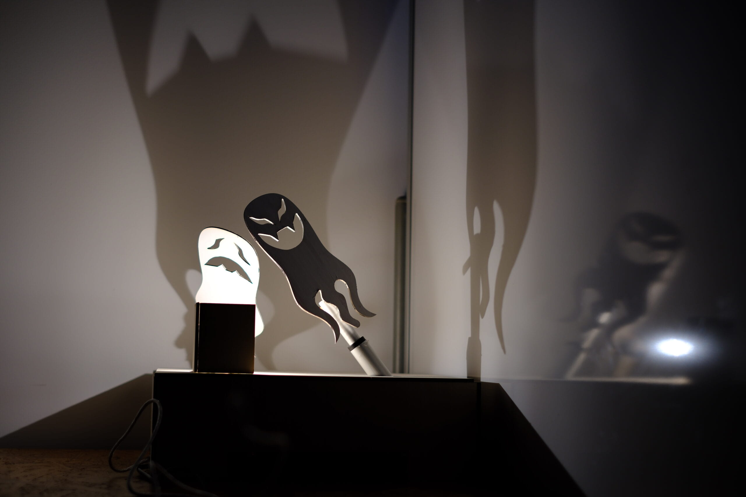
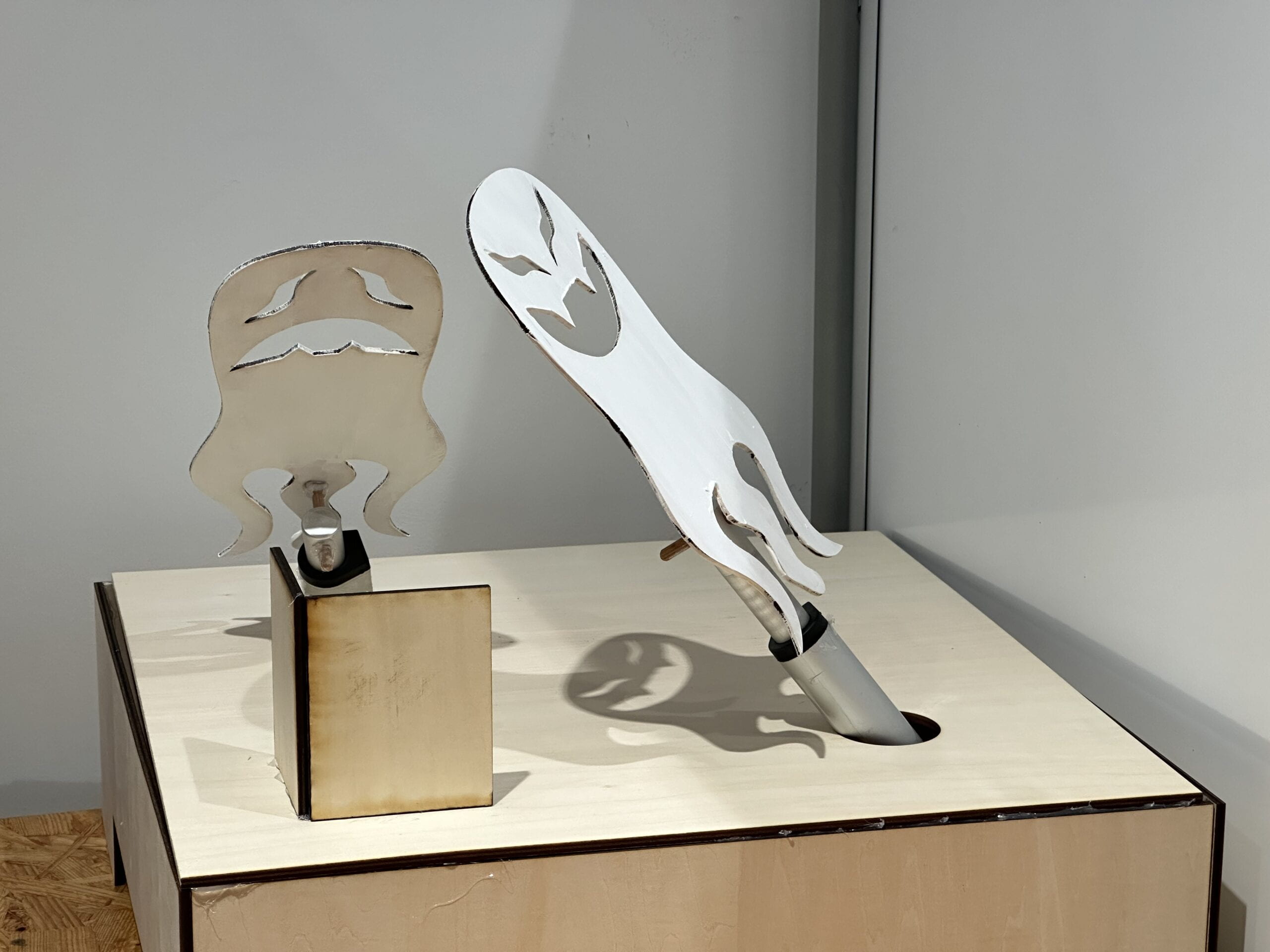
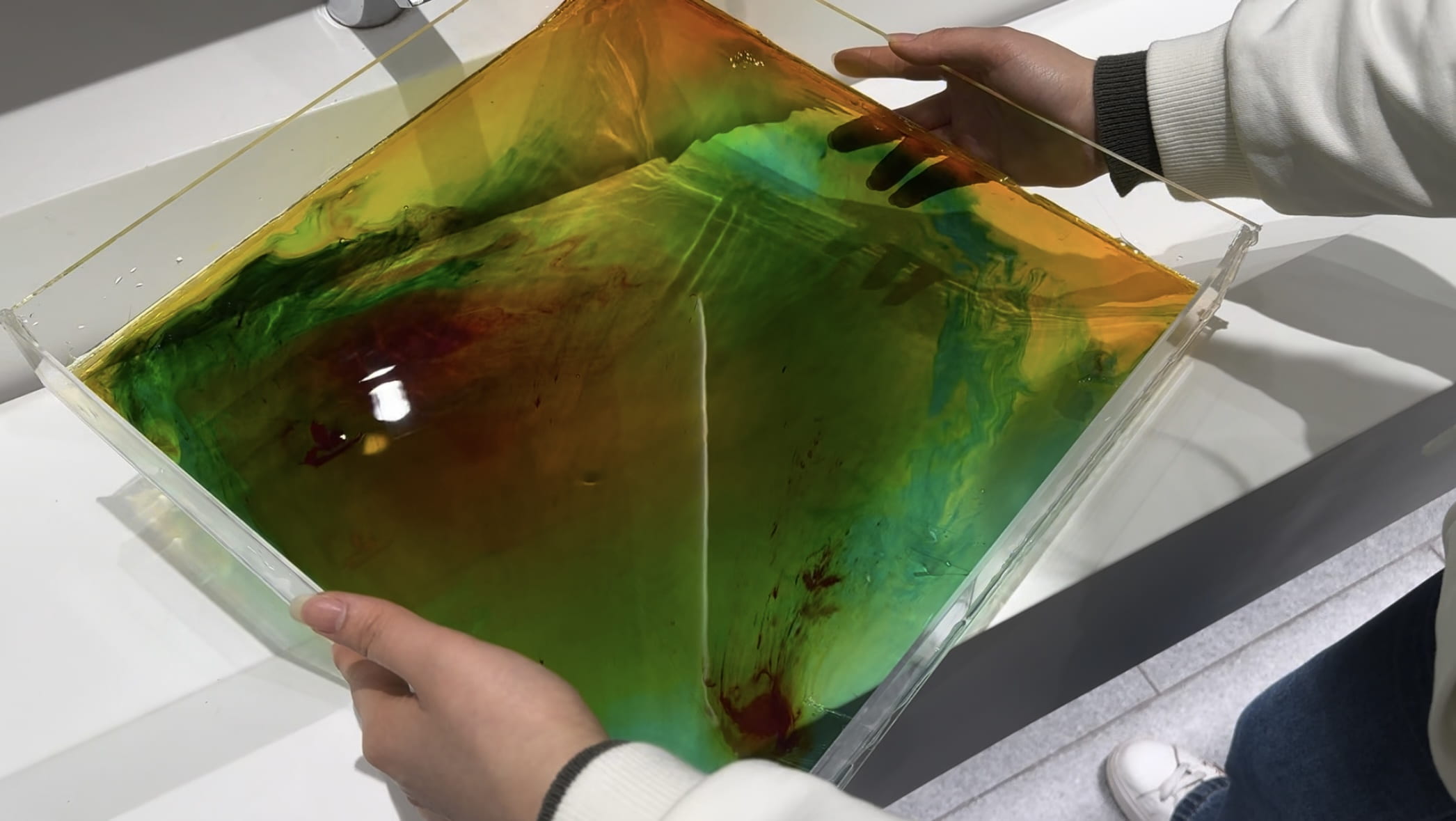
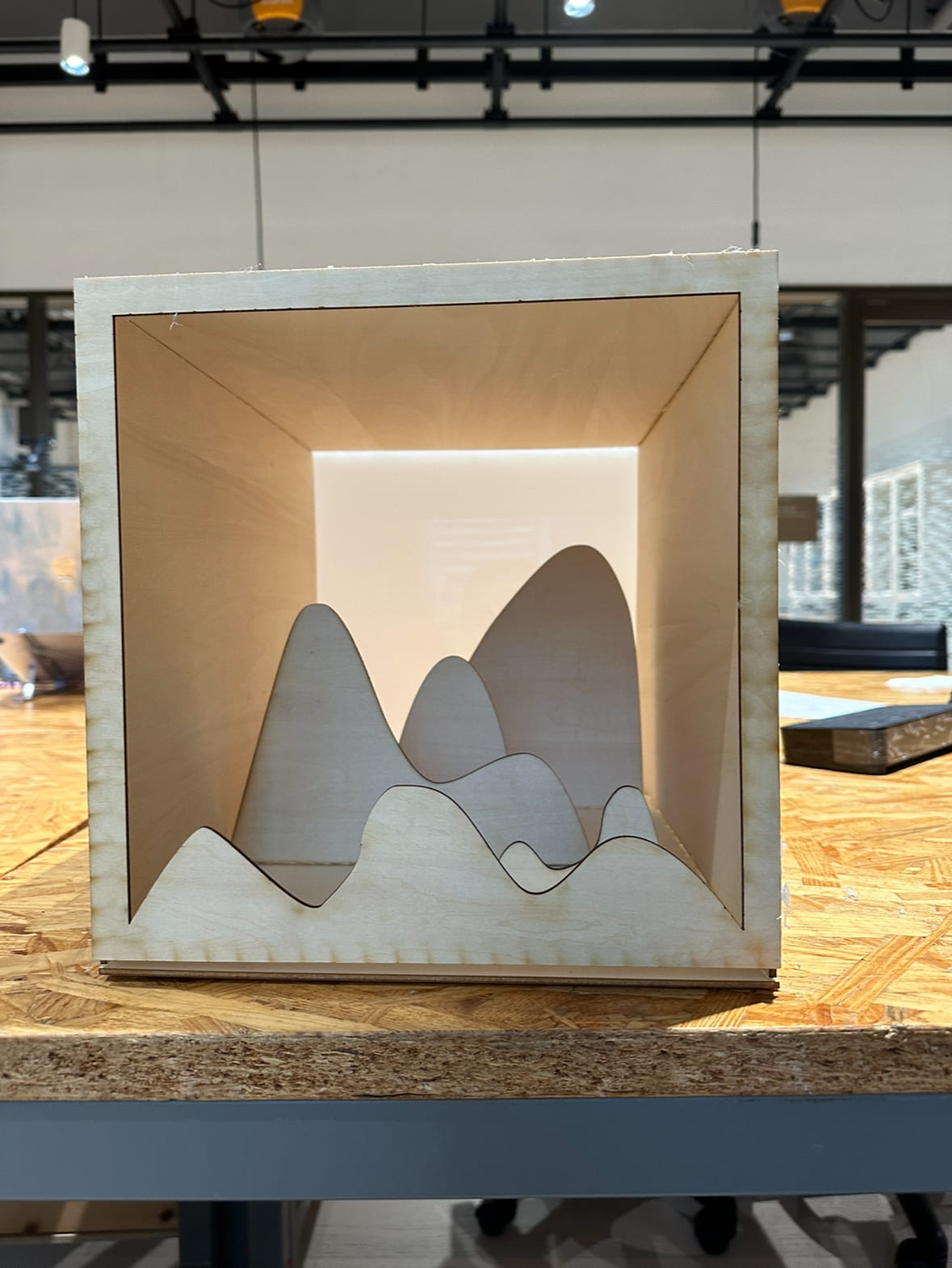
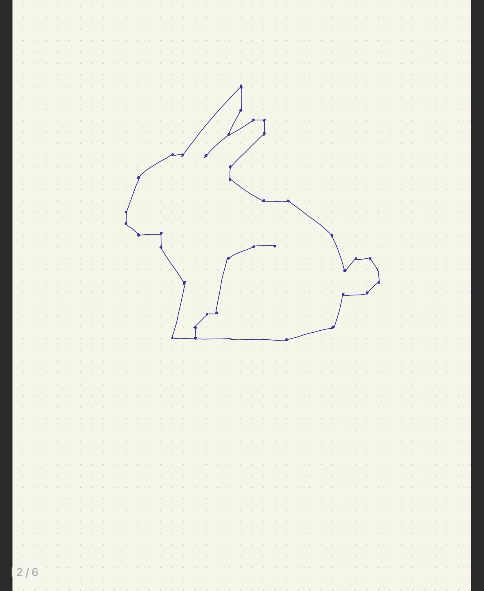
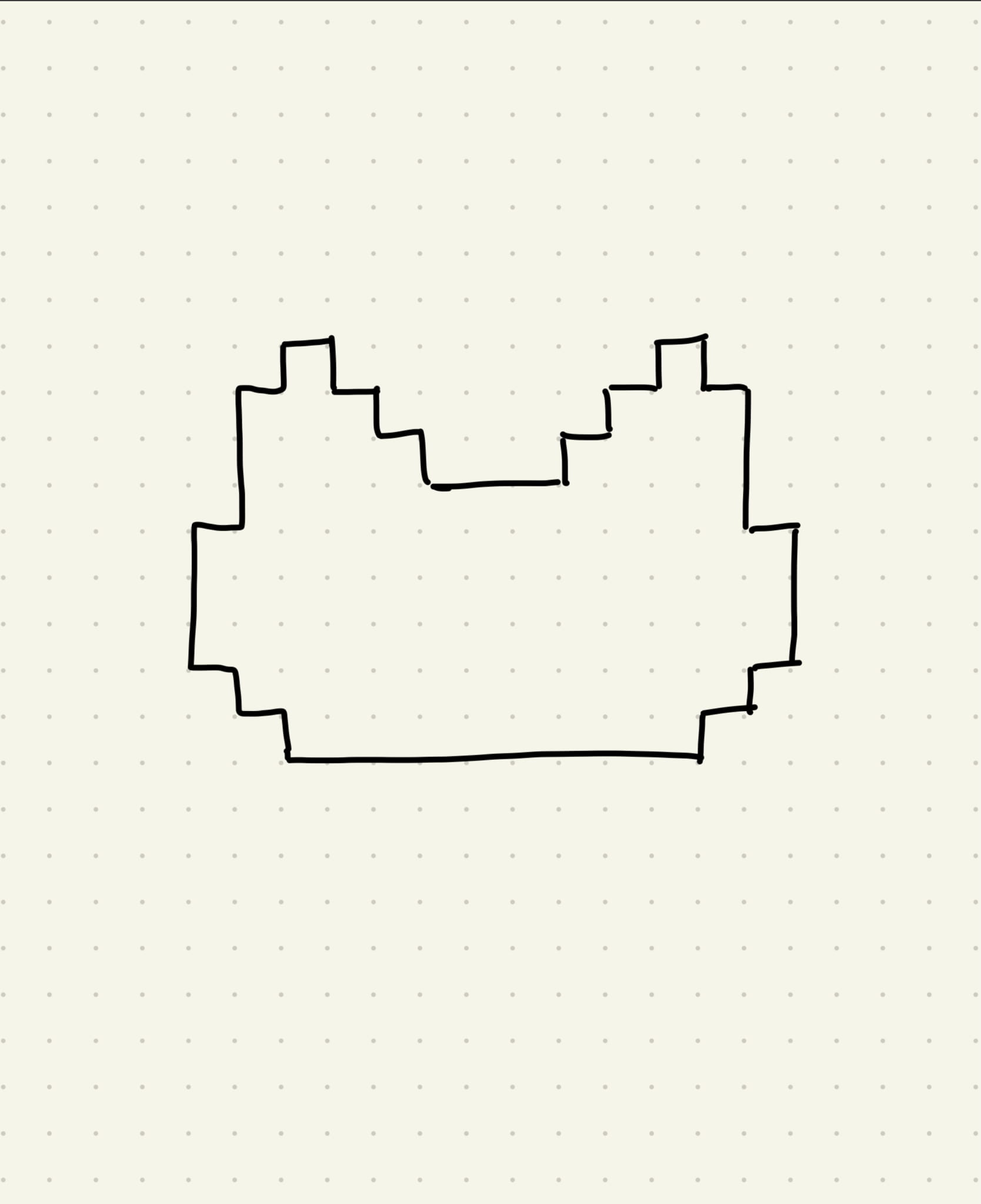
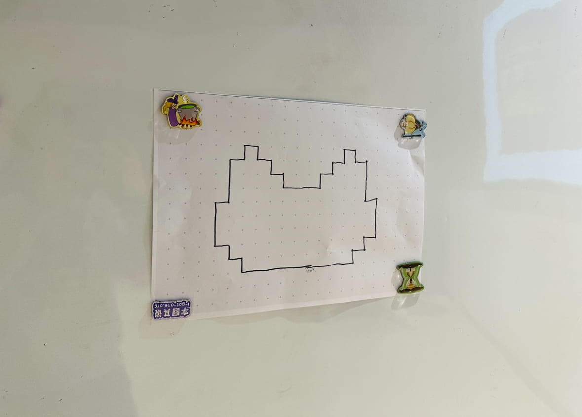
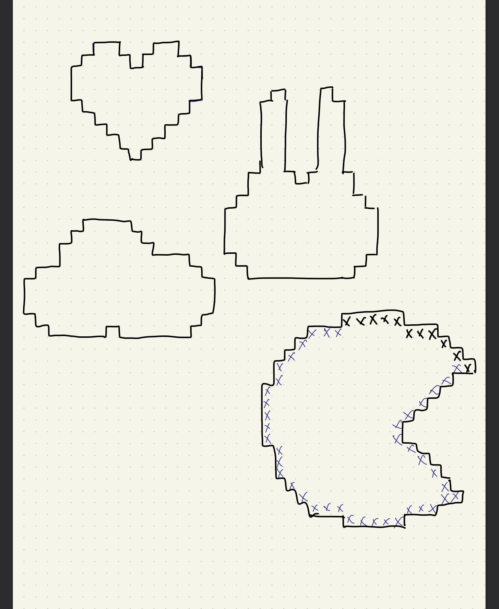
In the end, I drew this cat-like shape because the pointy ears would help to create enough concave so that there will be enough variations to the instruction and the shape is also somewhat good-looking. 

But still, the shape seemed a bit too easy to draw, so added a 60 second time restrain to make it more challenging . But telling from actual the presentation, I probably should’ve made harder, whether in the complexity of shape or the length of time, since the participants accomplished drawing the shape quite effortlessly. Though my estimation of setting a 60 second bar was quite accurate because it took them about 65 seconds, but because I timed it in a way that I was the only one who could see the clock, looking back, it would’ve been much better if everyone could see the time, especially the person who is drawing. I should also so enough user testing before presenting to improve my projects next time.

Here’s the finished piece of the presentation:

Here’s a video of the presentation: