A. PROJECT TITLE – YOUR NAME – YOUR INSTRUCTOR’S NAME
Guide: Escape from the maze
Jiaxiang (Eric) Yuan
Eric Parren
B. CONCEPTION AND DESIGN:
The original concept of this project is to create both a virtual maze and a physical maze within the same structure, requiring players to solve the puzzle of one maze based on information provided by the other. In the virtual maze, there is a character that follows the player’s guidance performed in the physical maze. Both mazes contain areas covered by darkness, and players must guide the character out of the maze through careful observations and persistent experimentation.
I conceived this idea when exploring a new interaction format that goes beyond the typical computer-keyboard interaction by connecting Processing and Arduino. In traditional maze games, players often control the character using keys like “w, a, s, d,” promoting trial and error to find the way out. However, I chose a different approach by constructing an identical physical maze and requiring players to press force sensors within the maze to guide the character. If the player makes a wrong move by pressing the wrong sensor, the character gets blocked, and the player must locate the character in the maze again, adding a time cost. This unique maze game encourages players to focus on observing the maze’s structure before controlling the character, providing them with a novel gaming experience.
While searching for examples on YouTube, I found the idea of creating a dark maze, which aligned well with my original concept (Inspired by this video: Processing – ‘Ghost Maze’ game – YouTube). The concept of darkness brought to mind visually impaired individuals. I recalled a charity event associated with a mobile game called Identity V, where visually impaired people were symbolized as wizards, and wands represented white canes (点亮每个孩子的“心光” 《第五人格》视障主题公益活动暖心预告! _《第五人格》官方网站 (163.com)). This inspired the use of a 3D-printed wand to activate a force sensor within the physical maze. This project aims to illustrate the challenges faced by visually impaired individuals in an engaging game format, fostering awareness and compassion for the visually impaired.
Attached are images of the 3D-printed wand:


The model for the wand is sourced from here: Harry Potter Wand by Alexbrn – Thingiverse
However, during the construction phase, I encountered challenges in designing intricate puzzles that necessitate connection and interaction between the two mazes. Additionally, my coding skills limited my ability to make multiple covered areas appear simultaneously, as detailed in the Fabrication and Production section. Recognizing the difficulty and not wanting to discourage players, I decided to modify the puzzle. Instead of intricate connections between the mazes, I opted for a scenario where the character in the virtual maze has limited sight, while the player can view the entire maze structure. This adjustment not only streamlined my workload but also made the game more comprehensible and enjoyable for the player.
Attached are the blueprints I created for my project:
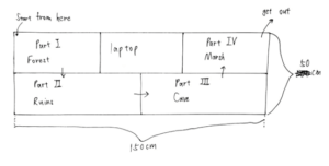
(overall size and shape)
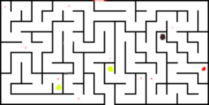
(forest)
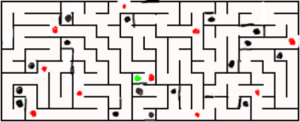
(ruins)
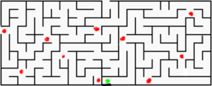
(cave)
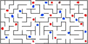
(ocean)
The mazes were generated using the Maze Generator at https://mazegenerator.net/
– Red spot: Force sensors (players guide the character by pressing these sensors).
– Green spot: Special events.
– Black/Brown spot: Tunnel (character transfers to another tunnel when walking on it).
– Blue spot: Deep water (character “dies” and returns to the start of the ocean part of the maze when walking on deep water).
Each of the four maze parts has unique features:
1. Forest: Designed to teach players how to play the game.
2. Ruins: Maximizes the use of tunnels.
3. Cave: Character’s sight decreases in this area.
4. Ocean: Maximizes the use of deep water.
List of events:
– Torch: Doubles the sight in the cave area.
– House: Removes darkness and shows the position of touch sensors on the screen.
– Cat: Guides the way in the ruins area.
When designing the maze, I adhered to the rule that pressing the wrong sensor at any position would lead to a wrong path and a collision with a wall. To add challenge, I strategically placed events opposite the correct path, making it harder for players to find. The maze structure was adapted to fit each area’s features. For example, Ruins had separate blocks with one or two tunnels, simplifying the game level. Cave had a linear layout to reduce confusion, and Ocean ensured every shortest route led the character into deep water.
My designs were instinctive, lacking systematic game design knowledge, and some structures of the maze may confuse players. With more knowledge before designing, I could have created more precise and interesting mazes.
I expected users to carefully observe the maze structure, explore freely, and try different events and features. However, during user testing, participants randomly pressed sensors without considering the maze structure. They quickly lost patience, finding the maze too challenging. To address this, I added instructions before the game and each area:
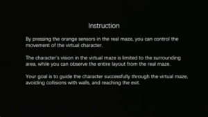
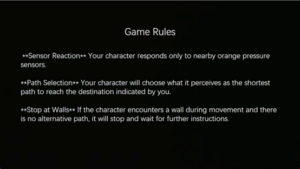
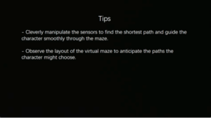
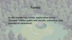
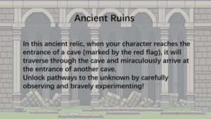
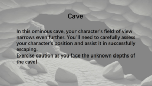
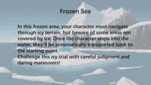
And also the images for the event:
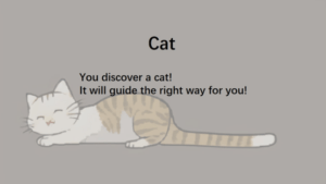
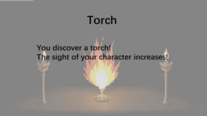
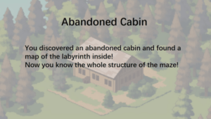
(all the background images are generated by Stable Diffusion with LORA “M_Pixel 像素人人” M_Pixel 像素人人 – v3.0 (morden_pixel) 现代像素 | Stable Diffusion LoRA | Civitai)
The modifications proved effective, as players clearly understood the objective of guiding the character out of the maze during the presentation and IMA Show. Additionally, the inclusion of images enhanced the immersive environment for players.
C. FABRICATION AND PRODUCTION:
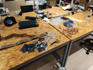
When selecting sensors, I experimented with both touch sensors and pressure sensors. I discovered that the touch sensor’s values were rather unstable, and objects other than fingers had difficulty significantly increasing its value. Additionally, its size posed a challenge as it was challenging to fit between the two walls in the maze. Consequently, I opted for force (pressure) sensors.
Attached is an image of the force sensors along with 1-meter-long wires:
Given that I needed to install 47 pressure sensors, and one Arduino Mega 2560 only provides 16 analog read pins, I made the decision to employ 4 Arduino Mega boards to manage the circuit. These boards communicate with each other through the RX/TX pins. (I gained insight into establishing communication between multiple Arduinos through this tutorial: Arduino 2 Arduino Communication VIA Serial Tutorial – YouTube) Below is the main code for communication:
while (Serial1.available()){
delay(1);
if(Serial1.available()>0){
char c = Serial1.read();
if (isControl(c)){
break;
}
readString1 += c; //makes the string readString
}
}
Q1 = readString1;
To streamline the workload, I utilized 3 Arduino Mega 2560 boards (referred to as slaves) to receive signals from pressure sensors. Additionally, one Arduino Mega 2560 (referred to as the master) was employed to collect signals from the slaves and transmit them to Processing. Below is the complete code for the Arduino boards:
https://drive.google.com/file/d/1gUjY9kesq36heEaFDPm6Si2EAdmMDHJi/view?usp=drive_link
https://drive.google.com/file/d/1l0cQwGEZuBZ8QlnaXohmttdRkc_Qljo3/view?usp=drive_link
https://drive.google.com/file/d/1z_7DL5cl0-ETMQGHGzjJzXwXtIdOowve/view?usp=drive_link
https://drive.google.com/file/d/19qhUFeGvHh9pqCsPHBMm8QsEeQeG1igt/view?usp=drive_link
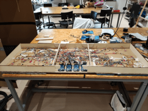
When working on my midterm project – Stepper Destroyer, my partner and I encountered various issues with wires, such as loose connections and insufficient length. To address these concerns, I purchased 1-meter-long wires for my final project, which proved to be effective. The extended length ensured that I didn’t have to worry about wires being unplugged due to force from other wires. I simply needed to ensure all wires were connected correctly and used a hot glue gun to secure them. Attached is a picture of the entire circuit:
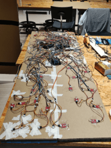
Even though it may appear messy, the setup functions well. I connected 47 touch sensors to 4 Arduino Mega 2560 boards and interlinked the Arduino Mega boards through TX/RX pins. Considering the straightforward nature of the connections, I believe a circuit diagram may not be necessary.
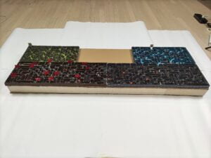
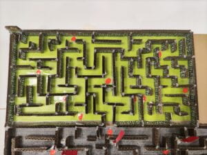
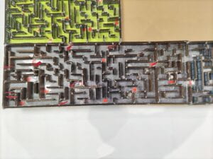
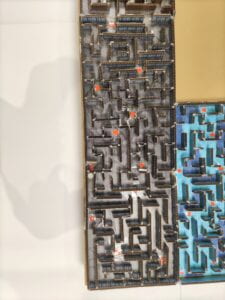
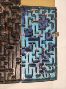
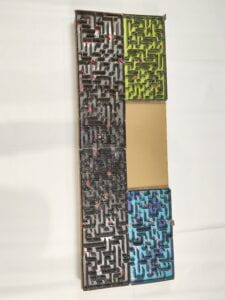
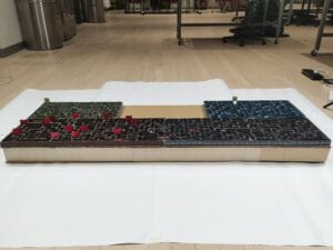
As for the physical maze, I printed out the four areas and affixed them to cardboard. Attached are the images:
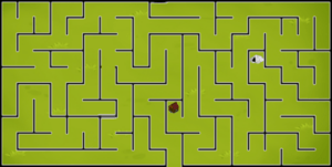
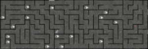
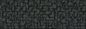
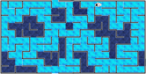
These images are the same in the two mazes. (physical and virtual)I learned and made these images myself through GIMP.
(The background images are from: OpenGameArt.org )
Forest background: Tower Defense – Grass Background | OpenGameArt.org
Ruins background: Handpainted Stone Tile Textures | OpenGameArt.org
Cave background: Handpainted Stone Floor Texture | OpenGameArt.org
Ocean background: Water | OpenGameArt.org
Water Textures | OpenGameArt.org
Other images:
House: hut | OpenGameArt.org
Tunnel: Cave entrance | OpenGameArt.org
Cat: 香炉 · 免费素材图片 (pexels.com)
Torch: [LPC] Animated Torch | OpenGameArt.org
Cat claw: Cat Claw PNG, Vector, PSD, and Clipart With Transparent Background for Free Download | Pngtree
Attached are the images of the building process of the physical maze:
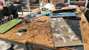
I chose cardboard as my material because it is easy to cut, and I needed to install 47 force sensors on the maze, requiring the drilling of 47 holes. While I could have achieved this through laser-cutting with plywood, it would have demanded precise design work on Cuttle (https://cuttle.xyz/), and I believed it would consume too much time.
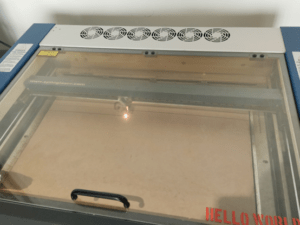
The sticks on the back are cardboard cut into 2.5-centimeter widths using a laser. Here is an image of my laser-cutting process:
I printed out the maze wallpaper and affixed it to the sticks. Subsequently, I used scissors to trim the sticks to the correct length and glued them onto the maze. Here are some photos documenting the process of affixing the walls:
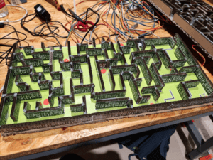
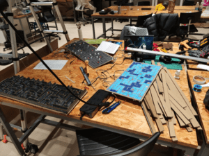
Affixing the wallpaper, cutting the sticks, and gluing them onto the cardboard was indeed a time-consuming and tedious task. Taking this into consideration, I’ll opt for a smaller scale in my future projects.
For the wallpapers, I sourced them from OpenGameArt.org
Forest wallpaper: Large forest background | OpenGameArt.org
Ruins wallpaper: Bricks | OpenGameArt.org
Cave wallpaper: Seamless cave in parts | OpenGameArt.org
Ocean wallpaper: Sea background 1920×1080 | OpenGameArt.org
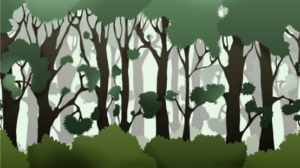
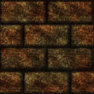
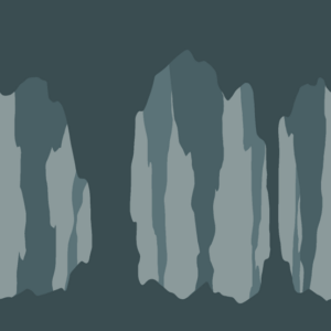
To conceal the wires and provide support for the cardboard, I used a laser-cutter to shape plywood pieces, embedding them along the sides of the maze. I opted for plywood due to its greater strength compared to cardboard.
Our fabrication lab assistant, Da Ling, provided assistance in creating two stands for my project. These stands were essential to prevent the cardboard from breaking under the weight of my laptop and the force applied during pressing. Attached is a picture of the stand:
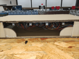
I secured the Arduinos and breadboards in an orderly manner by using hot glue. This arrangement facilitated the easy connection of the power supply and the linking of the Arduino (Master) with Processing. Here are the photos of the setup:
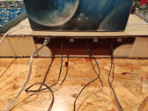
Subsequently, I added cardboard at the bottom to fully conceal the wires. Here is a photo of the finalized setup:
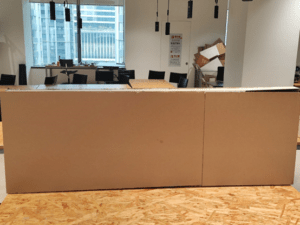
I utilized 3D printing to create small statues representing events and tunnels in the physical maze. All the models
were sourced from https://www.thingiverse.com/.
Here is a photo of the 3D printing process:
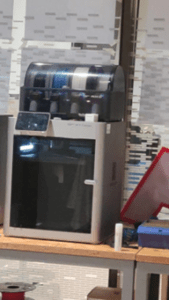
I acquired the 3D models from the following sources:
Tunnel: Cave Entrance by PrintedEncounter – Thingiverse
Torch:Torch by techappsgoodson – Thingiverse
Cat: Sitting cat low poly by Vincent6m – Thingiverse
House: Little Cottage (TabletopRPG house) by BSGMiniatures – Thingiverse
Subsequently, I 3D-printed these models, adjusting their size to fit within the physical maze. However, this resizing led to printing challenges, causing spaghetti in the 3D printer and making the removal of supports difficult. To mitigate these issues, I applied glue on the printing plate and enlarged the base. After several attempts, I successfully printed all the models.
During user testing, individuals with long nails expressed difficulty in directly pressing the pressure sensors. In response, I printed out some chess pieces to represent the character in the physical maze. Here is a photo of the chess pieces:
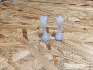
I obtained the models for the statues from this source: 3D Printable Chess Pieces by sivakaman – Thingiverse
The initial idea of using a 3D-printed wand to press the sensor failed due to the wand’s thinness, making it challenging to apply sufficient pressure to the sensor area. As a result, I recommended direct pressing with fingers.
Following user testing, where some participants indicated confusion about the starting and ending points of the game, I addressed this concern by adding “start” and “end” signs. The images were sourced from the following locations:
Startsymbol Auf Weißem Hintergrund Stock Vektor Art und mehr Bilder von Anfang – Anfang, Einzelner Gegenstand, Futuristisch – iStock (istockphoto.com)
End Sign – Road End Sign , SKU: K-6498 (roadtrafficsigns.com)
Here are the photos of the signs:
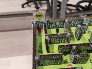
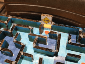
In response to feedback during user testing, where some testers reported difficulty in clearly seeing the tunnel model in the Ruins area of the physical maze, I addressed this concern by adding red flags to mark the tunnels. Here is the photo of the updated design:
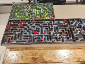
For the code in Processing, I used this code for receiving the signals from Arduino:
void getSerialData() {
while (serialPort.available() > 0) {
String in = serialPort.readStringUntil( 10 ); // 10 = ‘\n’ Linefeed in ASCII
if (in != null) {
print(“From Arduino: ” + in);
String[] serialInArray = split(trim(in), “,”);
if (serialInArray.length == NUM_OF_VALUES_FROM_ARDUINO) {
for (int i=0; i<serialInArray.length; i++) {
arduino_values[i] = int(serialInArray[i]);
}
}
}
}
}
(I copied it from here: 10.1 – Serial Communication 2 | F23 – Google Slides)
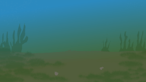
I divided the maze into four areas, with each section corresponding to a stage in Processing. To set the scene, I created the background image at the bottom. Here is how it looks:
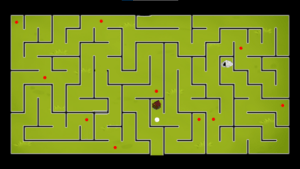
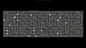
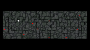
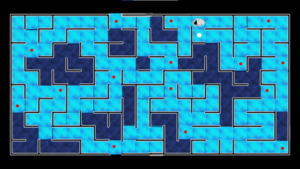
I represented the character using a white circle positioned based on its x, y coordinates. Additionally, I incorporated an image with a transparent circle in the middle to create the effect of darkness. Here is how it looks:
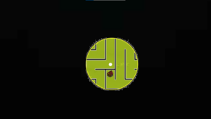
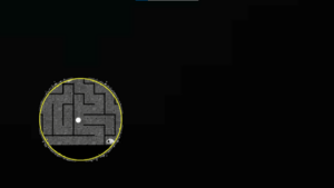

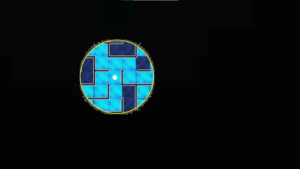
Thanks to Interaction Lab fellow Kevin for teaching me how to it.
The images I used to cover the maze:


I created the images using GIMP.
However, while this method was the simplest I could think of, it presented a challenge. It made it impossible to have one uncovered area move with the character while keeping another uncovered area fixed. As a result, I abandoned my original idea of having both mazes with some areas covered and others not. Instead, I shifted the interaction to a scenario where the character has limited sight in the virtual maze, and the player can see the entire structure of the physical maze.
Regarding character movement, after discussions with my professors, Professor Andy Garcia provided an example using the bezier() and bezierPoint() functions. Professor Eric Parren helped me convert it into a custom function. However, I found that I still needed multiple `if` statements to create the character’s route, leading me to abandon this approach.
Later, I considered making the character appear directly at the position guided by the player. However, I deemed this approach less immersive and potentially more confusing. Instead, I opted for a similar but more complex method. I divided each area into cells (e.g., 10×20 or 10×30) and set the position of each cell using an array. I derived this idea from the maze generator (Maze Generator), which prompted me to input the number of cells for width and height when creating the maze. Here is the code:
int x_position_forest_ocean[] = new int[20];
int x_position_ruins_cave[] = new int[30];
int y_position_forest_ocean[] = new int[10];
int y_position_ruins_cave[] = new int[10];
for (int i= 0; i < 20; i++) {
x_position_forest_ocean[i] = 105 + 90 * i;
}
for (int i= 0; i < 10; i++) {
y_position_forest_ocean[i] = 135 + 90 * i;
}
for (int i= 0; i < 30; i++) {
x_position_ruins_cave[i] = 90 + 60 * i;
}
for (int i= 0; i < 10; i++) {
y_position_ruins_cave[i] = 270 + 60 * i;
}
And I made the character move by reducing the frame rate to 4 and using multiple if statement. Here is an example:
if (position == 73) {
if (signal ==17) {
route = 57;
position =17;
signal = 0;
}
}
if (route == 57) {
if (count == 0) {
x = x_position_ruins_cave[17];
y = y_position_ruins_cave[5];
}
if (count == 1) {
x = x_position_ruins_cave[17];
y = y_position_ruins_cave[4];
}
if (count == 2) {
x = x_position_ruins_cave[16];
y = y_position_ruins_cave[4];
}
if (count == 3) {
x = x_position_ruins_cave[16];
y = y_position_ruins_cave[3];
}
if (count == 4) {
x = x_position_ruins_cave[16];
y = y_position_ruins_cave[2];
}
count++;
if (count == 5) {
count = 0;
route = 0;
}
}
I assigned a unique number to every possible position of the character and every possible route. To simplify my coding, I created an x-y coordinate axis. Here are my blueprints:
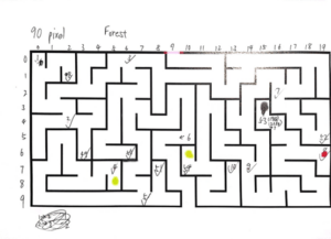
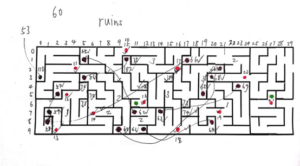
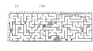
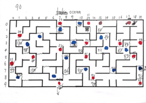
And this is a video of how the character moves:
void keyPressed() {
if (key == ‘r’ || key == ‘R’) {
restart = true;
}
}
This code allows players to position their character at the start of each area of the maze based on the character’s current location. In case of encountering bugs, players can press “r” to restart. I implemented this feature as there were a few remaining bugs in the code, and time constraints limited extensive testing and debugging.
To enhance the gaming experience, I incorporated background music for each area, all sourced from OpenGameArt.org
Forest music: forest | OpenGameArt.org
Ruins music: Ancient Ruins | OpenGameArt.org
Cave music: Tecave | OpenGameArt.org
Ocean music: Ice Mountain | OpenGameArt.org
Due to the complex method I chose for character movement, where I manually defined each route, my Processing code extends to 11,475 lines, surpassing the maximum limit of the draw() function.
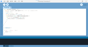
Professor Andy Garcia taught me to make each state into a custom function to save the space in function draw (). It works well.
Here is the full code for Processing:
https://drive.google.com/file/d/1ha_S5wtQmlBnEyINp5OY32bdkMIqjSWd/view?usp=drive_link
The data for Processing:
https://drive.google.com/drive/folders/1DKtQRijOefecR16PRM-a-vVHoXcJltmC?usp=drive_link
D. CONCLUSIONS
The objective of my project was to develop an immersive game that not only captivated users but also fostered awareness and empathy for the visually impaired. Although the emphasis leaned more towards the gaming experience rather than explicitly representing the challenges of the visually impaired, user testing and feedback from the IMA Show suggested that players found the game both challenging and fulfilling. However, upon revealing that the character they guided represented visually impaired individuals, players expressed surprise. Striking a balance between the gaming aspect and raising awareness posed a challenge, but I am content with the final outcome.
In the production phase, I initially didn’t anticipate writing such an extensive amount of code. Faced with the choice of reducing workload, learning advanced algorithms, or tackling the heavy but straightforward tasks, I opted for the latter due to my ambitious goal, time constraints and the uncertainty associated with learning complex algorithms. Despite the challenges, I successfully completed this sizable and intricate project as an individual effort within 14 days, which is a source of pride for me.
However, I believe there is considerable room for improvement in my project. While it boasts an imposing size and workload, it lacks the finer details. During the project’s design phase, I relied on instinct to infer player actions, making it appealing to experienced gamers who can swiftly grasp the game’s mechanics and passionately solve puzzles. Fortunately, at the IMA Show, I encountered two such users who were deeply engrossed in the game and provided glowing feedback.
This aligns with my vision of interaction, where users can input, process, and output information efficiently within my project. Users visually tracked position changes on the screen, considered the character’s location in the virtual and physical mazes, selected the appropriate sensor, and pressed it. The sensors transmitted signals to Processing, prompting the character to move, creating a continuous cycle of interaction. This linear, multi-step engagement aligns with my definition of a positive interactive experience.
However, some users found my project overly complex. At the IMA Show, there were individuals seeking something cool and advanced, displaying impatience with the detailed instructions. They hastily pressed sensors randomly, observed no immediate changes, and either left or sought guidance. Additionally, as my project is a game, it attracted many kids who, despite their enthusiasm, struggled to solve the puzzles independently. Consequently, I found myself needing to guide each child individually, resulting in exhaustion.
In my future project designs, I plan to prioritize simplicity while striking a balance between ambitious goals and intricate details. The aim is to create an aesthetically appealing project with a complex structure that is accessible to everyone. I envision a project that can be enjoyed without excessive deliberation, yet still offers a rewarding experience for those who appreciate careful consideration and creative design. Achieving this requires enhancing my skills and collaborating with an ambitious and skillful partner in the next endeavor.
For the current project, given more time, I would enhance the user experience by integrating 47 LEDs alongside the pressure sensors. Additionally, I would refine the structure of certain maze elements to ensure they make more sense to users. Furthermore, I’d optimize the sensitivity of some sensors to better respond to pressure. These adjustments aim to not only improve the project’s overall functionality but also enhance user engagement and satisfaction.
This is my first attempt at designing a game independently, and prior to embarking on this course, I had no coding skills. Throughout this project, I’ve not only gained technical expertise but also expanded my intellectual horizons. I’ve discovered that I possess the capability to bring my ambitious, and at times even seemingly crazy, ideas to fruition. However, it’s evident that there’s still a considerable journey ahead.
The substantial workload I assigned myself during this project serves as a stark reminder of my limited skill set and underscores the importance of teamwork. While I’ve been able to realize ambitious goals, the experience has highlighted the significance of paying attention to details as much as addressing complexity. Striking a balance is key – achieving ambitious objectives is gratifying, but the true measure of success lies in ensuring that all users can fully enjoy and comprehend my project.
E. DISASSEMBLY
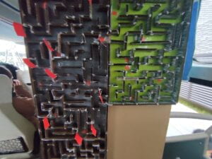
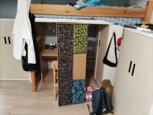
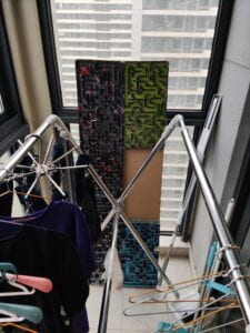
I bought all the equipment and most materials myself (47 force sensors, 4 Arduino Mega 2560, 10 100×100 cm cardboard, 200 100 cm male-to-male wires) and borrowed nothing from Equipment Room and Interaction Lab so that I can take my project home. Attached are the photos of my project taken to dorm:
F. APPENDIX
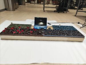
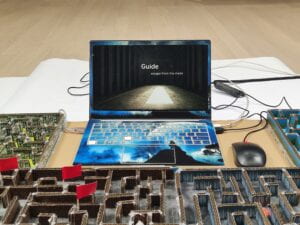
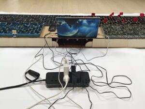
the appearance of the physical maze:
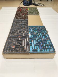
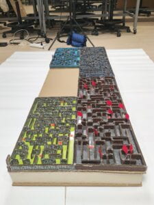
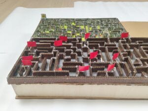
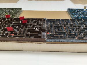
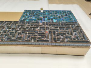
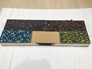
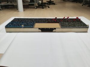
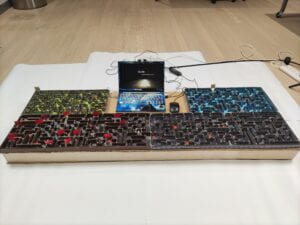
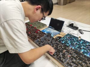
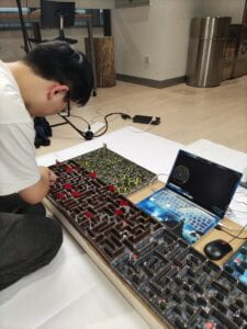
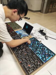
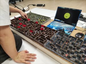
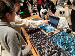
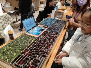
photos of playing the game:
the whole process of normal route of the game on screen:
shortcut 1:
shortcut 2:
event cat:
event house:
event torch:
fastest route (using restart):
wandering around (walking every wrong route):