Arduino
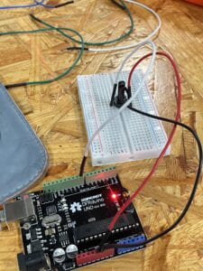
As for the Arduino physical controller, I chose this variable resistor (it may not be called that, I’m not sure about the name). I finished the wiring part quickly since it was pretty easy. All I needed to do is connect the resistor, one top to the pin, and the other two to GRD and 5V. Here’s a picture of the wiring connection.

Then I was going to write the codes of Arduino. I opened the SerialRecord example library and opened the SendSingleValue example. And also I opened another example in Arduino. Then I combine the two example code together, and it was like the below:
/*Analog InputDemonstrates analog input by reading an analog sensor on analog pin 0 andturning on and off a light emitting diode(LED) connected to digital pin 13.The amount of time the LED will be on and off depends on the value obtainedby analogRead().The circuit:- potentiometercenter pin of the potentiometer to the analog input 0one side pin (either one) to groundthe other side pin to +5V- LEDanode (long leg) attached to digital output 13 through 220 ohm resistorcathode (short leg) attached to ground- Note: because most Arduinos have a built-in LED attached to pin 13 on theboard, the LED is optional.created by David Cuartiellesmodified 30 Aug 2011By Tom IgoeThis example code is in the public domain.https://www.arduino.cc/en/Tutorial/BuiltInExamples/AnalogInput*/#include "SerialRecord.h"SerialRecord writer(1);int sensorPin = A0; // select the input pin for the potentiometerint ledPin = 13; // select the pin for the LEDint sensorValue = 0; // variable to store the value coming from the sensorvoid setup() {// declare the ledPin as an OUTPUT:pinMode(ledPin, OUTPUT);Serial.begin(9600);}void loop() {// read the value from the sensor:sensorValue = analogRead(sensorPin);// turn the ledPin ondigitalWrite(ledPin, HIGH);// stop the program for <sensorValue> milliseconds:delay(sensorValue);// turn the ledPin off:digitalWrite(ledPin, LOW);// stop the program for for <sensorValue> milliseconds:int value = millis() % 1024;writer[0] = sensorValue;writer.send();// This delay slows down the loop, so that it runs less frequently. This// prevents it from sending data faster than a Processing sketch that runs at// 60 frames per second will process it. It also makes it easier to debug the// sketch, because values are received at a slower rate.delay(20);} |
But there was no need to have the LED part, which was included in the example code, so I just deleted them. And at first, the Arduino part was done.
Processing
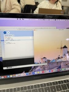
In the Processing part, I chose to use the image, so I downloaded a landscape of Santorini image on google. Then I referred to slide 22 and learned how to play the image on the sketch of Processing. At first, I had a problem that my image was not in this Processing document, but I found out that I did not add the “jpg” suffix to the image name when I entered it. Once I added it, the image was displayed without any problems.

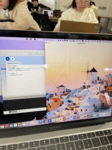
But I found something wrong with the size of this image, so I edited the size in the code and the image was displayed in full.

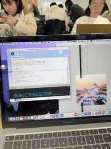
Then I opened the SerialRecord example of Processing, which was ReceiveSingleValue. And I combined this and the displaying image one. When I ran the code, though the image could zoom in and zoom out according to the variable resistor on the breadboard, there were several lines on the screen.

So I added a black background to the sketch and at the end the code of Processing was like the below:
PImage photo;
|
So finally, when Arduino and Processing’s code run together, the size of the image in Processing’s sketch will change according to the movement of the variable resistor connected to Arduino. The final result video looks like this.
Reference
Picture: https://www.klook.com/en-HK/city/405-Santorini-things-to-do/