Task #1: Make a Processing Etch-A-Sketch
For the first individual task, we needed to draw an Etch-A-Sketch, by using SerialRecord to connect Processing and Arduino as well. In this task, Processing needs to send the value, and Processing is the receiver of the value.
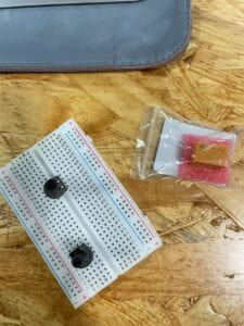
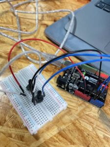
I first built the circuit to send two analog values from Arduino to Processing via serial communication using potentiometers. This step isn’t difficult or unusual, so I moved on quickly. Then I opened the “SendMultiple value” example and created a sketch to read the two serial values. I uploaded the code to the Arduino board and verified that the code and potentiometers were functional. The results demonstrated that both are operational; as I twisted each potentiometer, the serial values displayed on the screen changed.


Then I started to modify the “RecieveMultipleValue” example on Processing with the help of Kaylee, the learning assistant, and the whole process went smoothly too.
This task’s interaction occurred when I twisted the potentiometers to change the position of the circle on the screen. After I twisted the potentiometer, the serial values on Arduino were sent to Processing, which then processed the values and changed the position of the circle via the x and y axes.
Here’s the documentation video:
The Arduino Code:
#include "SerialRecord.h"// Change this number to send a different number of valuesSerialRecord writer(2);void setup() {Serial.begin(9600);pinMode(A0, INPUT);pinMode(A1, INPUT);}void loop() {int sensorValue1 = analogRead(A0);int sensorValue2 = analogRead(A1);writer[0] = sensorValue2;writer[1] = sensorValue1;writer.send();// This delay slows down the loop. This can make it easier to debug the// program.delay(10);} |
The Processing Code:
import processing.serial.*;
import osteele.processing.SerialRecord.*;

Serial serialPort;
SerialRecord serialRecord;

void setup() {
  fullScreen();


  String serialPortName = SerialUtils.findArduinoPort();
  serialPort = new Serial(this, serialPortName, 9600);

  // If the Arduino sketch sends a different number of values, modify the number
  // `2` on the next line to match the number of values that it sends.
  serialRecord = new SerialRecord(this, serialPort, 2);
}

void draw() {
  background(0);

  serialRecord.read();
  int value1 = serialRecord.values[0];
  int value2 = serialRecord.values[1];


  float x = map(value1, 0, 1024, 0, width);
  float y = map(value2, 0, 1024, 0, height);
  fill(255);
  circle(x, y, 60);
}
And how to modify the code to turn it into lines, at first I thought it was very simple. I drew a line on Processing and changed its position to (x, y, x, y), but I soon realized how can the beginning of the line and the end of the line be the same? So with Kaylee’s help, I added prevaluex and prevaluey.
The Processing Code:
import processing.serial.*;
import osteele.processing.SerialRecord.*;

Serial serialPort;
SerialRecord serialRecord;
float preValuex;
float preValuey;

void setup() {
  fullScreen();
  preValuex = 0;
  preValuey = 0;
  background(0);

  String serialPortName = SerialUtils.findArduinoPort();
  serialPort = new Serial(this, serialPortName, 9600);

  // If the Arduino sketch sends a different number of values, modify the number
  // `2` on the next line to match the number of values that it sends.
  serialRecord = new SerialRecord(this, serialPort, 2);
}

void draw() {


  serialRecord.read();
  int value1 = serialRecord.values[0];
  int value2 = serialRecord.values[1];

  float x = map(value1, 0, 1024, 0, width);
  float y = map(value2, 0, 1024, 0, height);
  stroke(255);
  strokeWeight(20);
 line(preValuex, preValuey, x, y);

 preValuex= x;
 preValuey= y;

}
Task #2:
Ragnor was my partner, and we started by figuring out the procedures for task 2. Initially, we planned to create the Arduino and Processing code separately and then combine them at the end. Shake wrote the Arduino code, and I wrote the Processing code. My goal for the Processing section was to create a circle that moved continuously from the left to the right side of the screen and then from right to left. And the circle had to send a signal to the Arduino board every time it reached the side.
Ragnor wrote the Arduino part, but when Processing came with our Arduino, it just didn’t work, I didn’t know what was wrong. Ragnor and I worked on the 826 for a long time on Friday afternoon, but didn’t find the problem, Ragnor told me it was the Arduino’s Code that was wrong and Steve came to help us. Finally we found that the frequency of send value was too fast to cause the servo on the receive side to not move, we adjusted this and the whole program finally ran smoothly.
But we didn’t add anything to the servo, so it looks less complete overall.
The Processing Code:
import processing.serial.*;
import osteele.processing.SerialRecord.*;

float x = 0;
float y;
int speed = 10;

Serial serialPort;
SerialRecord serialRecord;

void setup() {
fullScreen();
y = height/2;
serialPort = new Serial(this, "COM8", 9600);
serialRecord = new SerialRecord(this, serialPort, 1);
}

void draw() {
background(0);
circle(x, y, 20);
x = x + speed;
if(x > width){
speed = -10;
serialRecord.values[0] = 1;
serialRecord.send();
}
if (x < 0){
speed = 10;
serialRecord.values[0] = 0;
serialRecord.send();
}
delay(50);
}
The Arduino Code:
#include "SerialRecord.h"
#include <Servo.h>

Servo myservo1;
Servo myservo2;

SerialRecord reader(1);

void setup() {
 myservo1.attach(8);
 myservo2.attach(9);
 Serial.begin(9600);
}

void loop() {
  reader.read();
  Serial.println(reader[0]);
 if(reader[0] == 0){
  myservo1.write(90);
  delay(500);
  myservo1.write(0);
 }
 if(reader[0] == 1){
   myservo2.write(90);
   delay(300);
   myservo1.write(0);
 }
}
Reflection
I think the 2nd task is a bit difficult for us, we needed to complete the process of processing send value and accepting value from Arduino independently, and also connect it with the servo. This independent process also made me understand more about coding, but if we had more time, I would like to add something to the servo to make this little project more complete and interactive.