Recitation 9: Digital Fabrication

In this recitation class, we needed to combine laser cut and a motor to make a rotatable object. Lesley and I were partners for this class! 

Step 1: Design

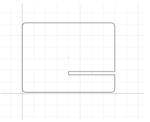
As for the design, we used cuttle.xyz, which is a website introduced in class before. While doing the stand design, I was in charge of the right side one. It was not hard, but we should carefully follow the instruction to pay attention to the units, data, location. 
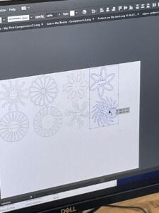
As for the pattern design, I watched the instructional video and then designed a figure inside the circle of the specified size and then duplicated it several times by building groups, and this figure I designed for the outside part was finished.
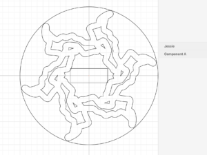
Then, I exported 2 of my files and went to 823 fabrication lab to laser cut.

Step 2: Laser cut

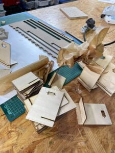
We were the first ones to go to laser cut and we found that the professors had already cut the stands in advance on wooden boards. All we needed to cut was the pattern of our own design for the spin.

The rectangle in my design was inside my pattern and didn’t intersect with my pattern, so printing down my pattern was going to break. So Andy made some adjustments to it. Finally it was successfully cut out.
Step 3: Assemble 

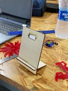
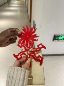
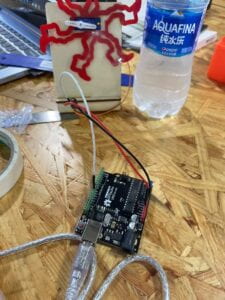
There was nothing wrong with the process of assembling our stand, and there was nothing wrong with the wiring on the Arduino as well. However, we found that the servo and the acrylic board we cut were a bit unassembled, so we taped them to make them fit together, although not very firmly.

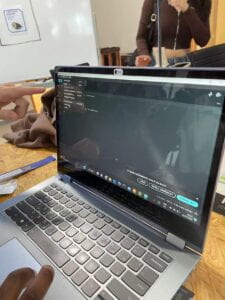
Both Lesley’s and my computer had a problem with the Processing version, and we couldn’t find the example in the library, so we borrowed Jason’s computer to run the code, and we found that ours ran smoothly.
 

Reflection

I found this class very interesting and I really liked the use of cuttle.xyz which is new to us, this graphic design is very attractive. We will also use laser cut in our final, so I have been watching the steps carefully. One of the shortcomings of our design is that Lesley and I didn’t pay much attention to which cut would be in front and which would be behind, so his design was smaller than mine but behind my board, which was not well thought out.
Final Project: Essay

Project title: Two-player drumming rhythm game

Project Statement of Purpose:

When we were thinking about this project, we considered that college students are generally under high stress, so we wanted to design a game that could relieve people’s stress in a fun way. So we came up with the idea of a rhythm game, but we felt that a one-player game was too basic, and we wanted to have two players collaborate on this game, so we wanted to design a rhythm game that two players would work together to play. We think that with this kind of teamwork players can feel more fun and engaged.

Project Proposal Plan:

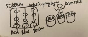
Generally, what we want to do is a rhythm game for two players. The main format we use is to display different color blocks on the screen according to a certain clip of music, and players will have different color drums in front of them, which color appears on the screen players need to hit the corresponding color drum. We also chose the drums because we felt that the drums would allow more physical interaction with the players, and the players moved their upper limbs instead of just their fingers. To make this more cooperative for two players, we decide to add some mixed colors, for example, if green appears on the screen, the players need to hit the yellow and red drums at the same time. We will also have three modes for players to choose from, easy medium and hard. These are the ways Sid and I came up with to make the game more engaging and more enjoyable for players, and also how to let them collaborate more.

We will also ask our friends and other classmates during the whole design process how we think we can improve the game to make it more interesting and more interactive for the two players.

Nov. 24th – Nov. 31st Building the programming part: finding similar code in open processing and making changes to it; Selecting a sensor: what sensor to connect to the drum to better deliver information accurately and without delay to the Arduino; we need to experiment and select.

December 1st – December 4th  Complete the programming design part, drum-making part (using laser cut), and wiring construction part. Basically, complete the project.

December 5th Check the whole project for problems and make minor changes

Context and Significance:

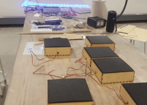
In my previous research, I came across a project called “UW-Makeathon: Laser Drums”, a project that uses laser cut technology to make drums, but its main theme is audio-visual integration, so it composes drums and fast LEDs. I got the inspiration from this project that I could use laser cutting to make drums and design a game with rhythm and music.

I think my vision of this project is quite in line with the definition of interaction, in my view it’s a fully interactive game. The color blocks on the screen mobilize the user to beat the corresponding drum, and the player’s response translates into a score on the screen that determines whether they can move to the next level of the game. The user is highly motivated and engaged, and it is not a one-sided input and output from either the project or the player.

Our game is unique in that it is not a single-player ordinary rhythm game, which already existed. It is a rhythm game where two players need to cooperate fully; two players control three drums and they need to decide for themselves how to distribute the tasks so that their motivation will be very actively mobilized.

I think the value of our project is that it is very simple; it is very easy to get started, and it brings remarkable results, that is, two players will definitely have a lot of communication when playing this game, will definitely cooperate, and will definitely be very natural and relaxed work in a team. This allows people to increase their communication with others in the game and also achieve the purpose of decompression and relaxation.

Recitation 8: Serial Communication

Task #1:  Make a Processing Etch-A-Sketch

For the first individual task, we needed to draw an Etch-A-Sketch, by using  SerialRecord to connect Processing and Arduino as well. In this task, Processing needs to send the value, and Processing is the receiver of the value.

I first built the circuit to send two analog values from Arduino to Processing via serial communication using potentiometers. This step isn’t difficult or unusual, so I moved on quickly. Then I opened the “SendMultiple value” example and created a sketch to read the two serial values. I uploaded the code to the Arduino board and verified that the code and potentiometers were functional. The results demonstrated that both are operational; as I twisted each potentiometer, the serial values displayed on the screen changed.


Then I started to modify the “RecieveMultipleValue” example on Processing with the help of Kaylee, the learning assistant, and the whole process went smoothly too. 

This task’s interaction occurred when I twisted the potentiometers to change the position of the circle on the screen. After I twisted the potentiometer, the serial values on Arduino were sent to Processing, which then processed the values and changed the position of the circle via the x and y axes.

Here’s the documentation video:

The Arduino Code:

#include "SerialRecord.h"
// Change this number to send a different number of values
SerialRecord writer(2);
void setup() {
Serial.begin(9600);
pinMode(A0, INPUT);
pinMode(A1, INPUT);
}
void loop() {
int sensorValue1 = analogRead(A0);
int sensorValue2 = analogRead(A1);
 
writer[0] = sensorValue2;
writer[1] = sensorValue1;
writer.send();
// This delay slows down the loop. This can make it easier to debug the
// program.
delay(10);
}

The Processing Code:

import processing.serial.*;
import osteele.processing.SerialRecord.*;

Serial serialPort;
SerialRecord serialRecord;

void setup() {
  fullScreen();
   

  String serialPortName = SerialUtils.findArduinoPort();
  serialPort = new Serial(this, serialPortName, 9600);

  // If the Arduino sketch sends a different number of values, modify the number
  // `2` on the next line to match the number of values that it sends.
  serialRecord = new SerialRecord(this, serialPort, 2);
}

void draw() {
  background(0);

  serialRecord.read();
  int value1 = serialRecord.values[0];
  int value2 = serialRecord.values[1];
 

  float x = map(value1, 0, 1024, 0, width);
  float y = map(value2, 0, 1024, 0, height);
  fill(255);
  circle(x, y, 60);
}

And how to modify the code to turn it into lines, at first I thought it was very simple. I drew a line on Processing and changed its position to (x, y, x, y), but I soon realized how can the beginning of the line and the end of the line be the same? So with Kaylee’s help, I added prevaluex and prevaluey. 

The Processing Code:

import processing.serial.*;
import osteele.processing.SerialRecord.*;

Serial serialPort;
SerialRecord serialRecord;
float preValuex;
float preValuey;

void setup() {
  fullScreen();
  preValuex = 0;
  preValuey = 0;
  background(0);

  String serialPortName = SerialUtils.findArduinoPort();
  serialPort = new Serial(this, serialPortName, 9600);

  // If the Arduino sketch sends a different number of values, modify the number
  // `2` on the next line to match the number of values that it sends.
  serialRecord = new SerialRecord(this, serialPort, 2);
}

void draw() {
  

  serialRecord.read();
  int value1 = serialRecord.values[0];
  int value2 = serialRecord.values[1];
 
  float x = map(value1, 0, 1024, 0, width);
  float y = map(value2, 0, 1024, 0, height);
  stroke(255);
  strokeWeight(20);
 line(preValuex, preValuey, x, y);
 
 preValuex= x;
 preValuey= y;

}

Task #2:

Ragnor was my partner, and we started by figuring out the procedures for task 2. Initially, we planned to create the Arduino and Processing code separately and then combine them at the end. Shake wrote the Arduino code, and I wrote the Processing code. My goal for the Processing section was to create a circle that moved continuously from the left to the right side of the screen and then from right to left. And the circle had to send a signal to the Arduino board every time it reached the side.

Ragnor wrote the Arduino part, but when Processing came with our Arduino, it just didn’t work, I didn’t know what was wrong. Ragnor and I worked on the 826 for a long time on Friday afternoon, but didn’t find the problem, Ragnor told me it was the Arduino’s Code that was wrong and Steve came to help us. Finally we found that the frequency of send value was too fast to cause the servo on the receive side to not move, we adjusted this and the whole program finally ran smoothly.

But we didn’t add anything to the servo, so it looks less complete overall.

The Processing Code:

import processing.serial.*;
import osteele.processing.SerialRecord.*;

float x = 0;
float y;
int speed = 10;

Serial serialPort;
SerialRecord serialRecord;

void setup() {
fullScreen();
y = height/2;
serialPort = new Serial(this, "COM8", 9600);
serialRecord = new SerialRecord(this, serialPort, 1);
}

void draw() {
background(0);
circle(x, y, 20);
x = x + speed;
if(x > width){
speed = -10;
serialRecord.values[0] = 1;
serialRecord.send();
}
if (x < 0){
speed = 10;
serialRecord.values[0] = 0;
serialRecord.send();
}
delay(50);
}

The Arduino Code:

#include "SerialRecord.h"
#include <Servo.h>

Servo myservo1;
Servo myservo2;  

SerialRecord reader(1);

void setup() {
 myservo1.attach(8);
 myservo2.attach(9);
 Serial.begin(9600);
}

void loop() {
  reader.read();
  Serial.println(reader[0]);
 if(reader[0] == 0){
  myservo1.write(90);
  delay(500);
  myservo1.write(0);
 }
 if(reader[0] == 1){
   myservo2.write(90);
   delay(300);
   myservo1.write(0);
 }
}

Reflection

I think the 2nd task is a bit difficult for us, we needed to complete the process of processing send value and accepting value from Arduino independently, and also connect it with the servo. This independent process also made me understand more about coding, but if we had more time, I would like to add something to the servo to make this little project more complete and interactive.

Final Project: Three Project Proposals

First: Dancing with the rhythm

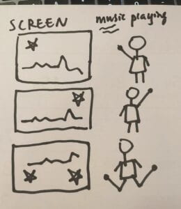
First I’m trying to come up with something to help University students release their pressure. Because I feel that the pressure on today’s college students is too heavy and something should be done to help them release their academic pressure. And the first thing that came to my mind was some simple and passionate way of exercise, so what exercise can be made into a project by us, I continued to think. Then I thought of the dancing machine, where people would step back and forth according to the instructions on the screen, and then score points based on how correctly they danced. So my first idea was a project somewhat similar to the dance machine, we wanted to wear sensors on the user’s hands and feet, and then follow the rhythm of the music we played, some images would appear on the screen, and people’s hands and feet would need to move according to the images and dance to the music. Depending on the performance of different users, users will also receive different rating feedback. I think dancing to the rhythm of the music is a very suitable way for college students to relieve stress, and it’s also a very engaging game.

Second: Punch to release pressure

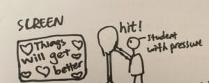
My second project idea was also aimed at reducing student stress, so I naturally came up with the idea of hitting something, like a boxing sandbag, etc. So I envisioned putting the pressure sensor in some soft material that can be punched, people can use our project to vent their emotions, and whenever they punch our project, some corresponding text and images will appear on the screen to further reduce the user’s pressure. These words can be encouraging words like “take your time, things will always get better”; they can also be some witty and humorous words. It doesn’t really matter what form they take, the main thing is that something will appear on the screen after people hit our project to make them feel better and less stressed.

Third: “Color-Drum-Rhythm” Game

My next project is still focused on the student community, I want to make a game between students, it can be a game of cooperation or competition between two people. Because I want people to fully engage, I plan to make a two-player cooperative game. And when designing the form of this game, I thought of the research I did earlier, the project about laser cutting drums. So I think this game can also be combined with music, it will be made into a rhythm game, the screen shows some color blocks, and the player needs to hit the corresponding drum according to the different colors. There may be several drums of different colors. I haven’t quite figured out exactly how to implement it, because it’s pretty difficult to make the drums and install the sensors, but the direction and format I think is a good idea: a two-player cooperative music rhythm game.

Final Project: Research

New thoughts about “interaction”:

What contributes to a successful interactive experience is a very insightful question. And at first, when we were doing the group project, we just thought of interaction as people and the machine having mutual input and output and that’s enough. So we made a robot that can provide different help according to the petrified state of the person, it was relatively intelligent, but the input provided by the people was actually not enough. And we had a kind of similar problem when we were doing our midterm. So the users just wore the heartbeat sensor on their ears and pressed the button, and that was basically all for what the users could do. Then we would show the visualized image of their heartbeat frequency and let them know how fast their heartbeat was. Though the feedbacks from the users were generally good, we still think that the interaction between users and our project was kind of lacking. The above is my further understanding of interactivity from my group project and midterm.

So now I think “interaction” should be more mutual and users need to do more input, and in turn, they will get a deeper experience. People will have a better experience in this project after the interaction is more in-depth, In the book, Ernest Edmonds says that “an interaction, be it with another human, an artwork, or a game, can influence internal states.” So I now think that interaction should also have a deeper impact on the user, rather than just staying in a momentary sensory experience.

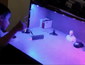
The first interactive project I chose isGesture Controlled Interactive Table Light.” This project mainly consists of a sensor and FastLED, and the user’s gestures will be transmitted to this sensor, and then FastLED will change the color of the light. I think its interactive part is successful, it fully changes the light color according to the user’s input, which is their gesture. And the color of the lights will have a mental impact on the user while the user is using this table light. So the combination of user input and the output of this project is well worth learning from.

The second interactive project I chose isUW-Makeathon: Laser Drums.The main body of the project is a number of drums made of laser-cut wooden boards that emit different types of sounds when struck, and are visualized on the neopixel. I think this combination of music and visuals and drums is very good. And I might work with music and instruments as well, and also apply some visual stuff to make the whole thing like a game.

Recitation 7: Neopixel Music Visualization

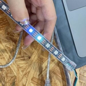
In this recitation class, we needed to use light strip in combination with Processing and Arduino, We were asked to connect the sound to the light strip and the light strip to the computer.

Task one:Test the NeoPixel

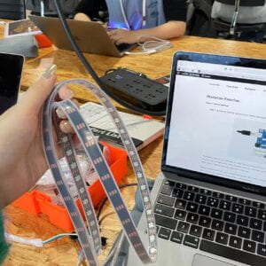
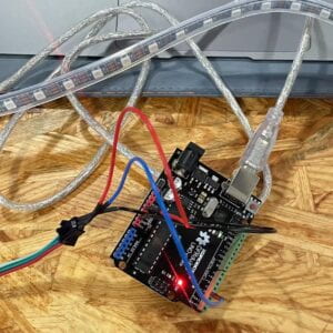
First, we were asked to connect the computer to the light strip and make sure the program was running properly. I built the circuit by using three jumper cables to connect the NeoPixel strips to the Arduino.

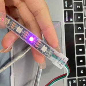
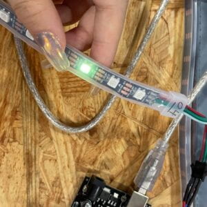
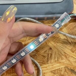
I downloaded the FastLed library and tested several examples, for example, I tested blink. The whole thing was running very smoothly. I also modified the code to make it flash a different color every other light


Task two: Use your computer to light up NeoPixels

I downloaded the Serial Record library before, so I started the second step directly. I tested my code with Serial Monitor and the whole process went well and smoothly. I had no problem with my Arduino, I programmed my Arduino with the code we had in class, which I simply copied and pasted from the link provided on the Recitation page. Then, I entered the serial values (CSV) of 1,255,0,100 into my Serial Monitor. The first value represents the pixel number, the second the content of red, then green, and finally blue. The outcome indicated that my Serial Monitor was operational.

But when I got to the third step of Processing part, my computer couldn’t run it for some reason. In the end, with the help of our professor, the students who were using Macbook air downloaded another version of the file and solved the problem.

Then we managed to implement the interaction between Precessing and Arduino at Fast Led. Although it’s not something I programmed myself, I understood the logic in general, and I thought it was pretty cool.

Here’s a documentation video:

Task three: Add Music!

This part was quite interesting that we downloaded a music clip from the internet and tried to visualize it. So I chose the music called “The Glimpse of Us” as the one going to be played and dragged the downloaded file into the Processing file. I replaced beat.aiff with joji.mp3. Then I also connected it to the Arduino’s FastLed, which means that when the song was playing, in addition to the screen displaying the video based on volume and rhythm, the FastLed’s light strip would also be displayed accordingly. I also modified the color of the screen visualization video according to the rhythm and style of the whole song.

But I also found some problems and did not find useful solutions, which was that the LED response to the music was relatively lagging. And when the amplitude of the music changes, for example, when the amplitude changes from high level to low level, the LED does not change. But overall I was still satisfied with the whole work. I feel that this class gave me a rough idea of the logic between Arduino and Processing.

But my video doesn’t seem to have recorded the part with the LED strip, but you can see from my code that I did include it.

Final Code:

import processing.serial.*;
import osteele.processing.SerialRecord.*;
import processing.sound.*;

Serial serialPort;
SerialRecord serialRecord;

int W;         //width of the tiles
int NUM = 60;  //amount of pixels
int[] r = new int[NUM]; //red of each tile
int[] g = new int[NUM]; //red of each tile
int[] b = new int[NUM]; //red of each tile


SoundFile sample;
Amplitude analysis;

void setup() {
  size(600, 200);
  W = width/NUM;


  // You can use this syntax and change COM3 for your serial port
  // printArray(Serial.list());
  // serialPort = new Serial(this, "COM3", 9600);
  // in MacOS it looks like "/dev/cu.usbmodem1101"
  //or you can try to use this instead:

  String serialPortName = SerialUtils.findArduinoPort();
  serialPort = new Serial(this, serialPortName, 9600);
  serialRecord = new SerialRecord(this, serialPort, 4);
  serialRecord.logToCanvas(false);
  rectMode(CENTER);

  // load and play a sound file in a loop
  sample = new SoundFile(this, "joji.mp3");
  sample.loop();

  // create the Amplitude analysis object
  analysis = new Amplitude(this);
  // analyze the playing sound file
  analysis.input(sample);
}

void draw() {
  println(analysis.analyze());
  background(75, 120, 237);
  noStroke();
  fill(125, 212, 77);

  // analyze the audio for its volume level
  float volume = analysis.analyze();

  // volume is a number between 0.0 and 1.0
  // map the volume value to a useful scale
  float diameter = map(volume, 0, 1, 0, width);
  // draw a circle based on the microphone amplitude (volume)
  circle(width/2, height/2, diameter);

int n = floor(map(volume, 0, 1, 0, 60));
  r[n] = floor(map(volume, 0, 1, 0, 255));
  g[n] = floor(random(map(volume, 0, 1, 0, 255)));
  b[n] = floor(random(map(volume, 0, 1, 0, 255)));

  serialRecord.values[0] = n;     // which pixel we change (0-59)
  serialRecord.values[1] = r[n];  // how much red (0-255)
  serialRecord.values[2] = g[n];  // how much green (0-255)
  serialRecord.values[3] = b[n];  // how much blue (0-255)
  serialRecord.send();            // send it!
} 

Recitation 6: Animated Poster

At the beginning of this poster, I made three dots, two moving from the left to the right of the screen and one moving from the right to the left. There was also a square moving on the screen, which would flash on the screen. Finally, I wrote the time and place of the IMA show on a white background. What bothers me about this poster is that if the dots move at normal speed, the square will be too fast to be controlled. So now the dot is moving very slowly in order to make the square move normally.

int x=0;
int y=808;
float z=0;
float o=0;
float p=40;
float q=60;

void setup(){
  size(1024,768);
}

void draw(){
  background(144,212,255);
   C1(x);
     frameRate(200);
   x++;
   if (x==width+40){
     x=-40;
   }
   
   C2(y);
     frameRate(200);
   y=y-1;
   if (y==width-808){
     y=808;
   }
   
    C3(x);
      frameRate(200);
   //x++;
   if (x==width+40){
     x=-40;
   }
   
   R1(z,o,p,q);
   frameRate(20);
   z=z+10;
   o=o+10;
   p=p+20;
   q=q+20;
}

void C1(int a){
  //鹅黄色
  fill(254,237,146);
  noStroke();
  ellipse (a,200,80,80);
}

void C2(int b){
   fill(254,237,146);
   noStroke();
   ellipse (b,400,80,80);
}

void C3(int a){
  //鹅黄色
  fill(254,237,146);
  noStroke();
  ellipse (a,600,80,80);
}

void R1(float c,float d,float e,float f){
  int r=int(random(255));
  int g=int(random(255));
  int b=int(random(255));
  fill(r,g,b);
  noStroke();
  rect(c,d,e,f);
  
    noStroke();
  fill(255);
  rect(206, 335, 800, 300);
  fill(0);
  textSize(50);
  text("IMA Fall 22 Show!", 240, 420);
  fill(0);
  textSize(25);
  text("Friday, December 16 | 6pm to 8pm", 240, 480);
  text("Location: 8th Floor", 240, 540);
  fill(190);
   circle(225, 380, 20);
   circle(225, 580, 20);
  
  
}

Homework

I really didn’t think the poster I made in class looked good, so I studied the homework outside of class. I drew a figure consisting of three circles, generated 100 of them, and followed the generated positions. I learned the use of “push” and “pop” in the previous lesson, and I used them. I also used keyPressed function to control them according to the instruction. When the “o” is pressed, the whole pattern will be laid out in a different way.

At first, the color choice was a bit weird, but then I edited it a bit. I defined three RGB variables and used the map function to map random numbers ranging from 0 to 255 into a specific range, resulting in visually harmonious colors.

First version:

Final version:

float r, g, b;
void setup() {
  size(1024, 768);
  background(255);
  for(int x= 0; x<10; x++){
  for(int y=0; y<10; y++) {
      r = map(random(255), 0, 255, 200 ,255);
      g = map(random(255), 0, 255, 180 ,240);
      b = map(random(255), 0, 255, 175 ,235);
 
   push();
   translate( random(0, width),random(0, height));
   //translate(y * 100,0);
   noStroke();
  fill(r,g,b);
  ellipse(60, 40, 60, 60);
  fill(253,255,156);
  ellipse(50,54, 52, 52);
  fill(r,g,b);
  ellipse(50, 55, 20, 20);
  fill(r,g,b);
  pop();
    }  
  }
}

void changePos(){
  background(255);
  for(int x= 0; x<10; x++){
    for(int y=0; y<10; y++) {
       r = map(random(255), 0, 255, 200 ,255);
      g = map(random(255), 0, 255, 180 ,240);
      b = map(random(255), 0, 255, 175 ,235);
 
 
   push();
   translate( random(0, width),random(0, height));
   //translate(y * 100,0);
   noStroke();
  fill(r,g,b);
  ellipse(60, 40, 60, 60);
  fill(253,255,156);
  ellipse(50,54, 52, 52);
  fill(r,g,b);
  ellipse(50, 55, 20, 20);
  fill(r,g,b);
  pop();
    }  
  }

}

void changeColor(){
  

}
void keyPressed() {
  if (key == 'o') {
    changePos();
  }
 
}

void draw(){

}

Recitation 5: Processing Basics

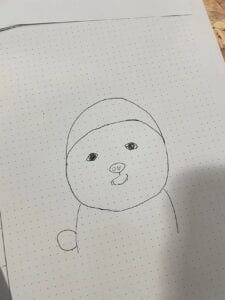
This is my Wechat profile, and I think it’s quite cute, so I chose to use Processing draw it. Since I’m not that good at drawing, here my sketch is not that pretty.

I drew the dog in a kind of symmetrical way because I thought it would be easier to draw it on Processing. And due to my absence from the previous class, when Rudi introduced the basics of Processing, it was even harder for me to apply Processing to draw pictures and this kind of work.

But I browsed Processing’s website and learned how to draw some basic shapes, such as ellipses, rectangles, and lines. Kaylee, my learning assistant, and Sid, my friend, also taught me how to fill in the colors and how to find the parameters of the desired color.

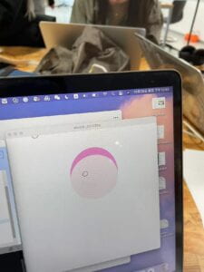
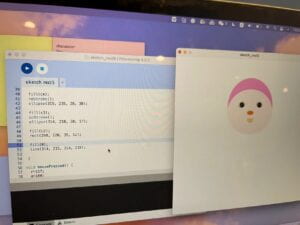
So I started the first try of coding with Processing. I started the drawing with a big pink ellipse. But I just needed a small part of it to be the pink hat of the puppy. And then I draw a relatively smaller ellipse inside the big one in lighter pink, to be the face. 

Then I’m going to start drawing the eyes. The dog’s eyes are tilted in the sketch, so I want to draw a tilted eye too. And this means I needed to rotate the ellipses as the eyes on the puppy’s face to some degree. But I really had no idea how to do it, so I turned to my professor Rudi for help.

Rudi told me to use “rotate” to do this, and applied “push” and “pop”. The code was like this:

push();

  translate( 275, 178);

  rotate(radians(-25));

  ellipse(0, 0, 26, 20);

  pop();

After knowing how to rotate any angle, I easily drew the eyes, with ellipses of different sizes. So the puppy was almost done, just a nose and a tongue were needed. And I quickly coded a nose. Then I saw the prompt, it said if you want, you can make some moving animation.

And I thought if the color of the puppy’s hat could change, that would be very cool. So I asked my friend, the learning assistant in our class–Kaylee, about how to make the animation move.

She asked me whether I wanted to make the color change automatically or when I click the mouse, it changes once. I chose the mouse clicking changing mode. 

So she introduced the “mousePressed” function to me, and told me to make the color value of the hat some variables. Then after the mousePressed instruction, I could easily change the color of the hat. I got her point and coded another blue hat. After clicking the mouse, the hat would change into blue.

It’s very cool.

And after the recitation class, I added a tongue and two ears to the puppy. It then looked very cute, at least to me!

Here’s the code:

int r = 245;

int g = 163;

int b = 213;

void setup() {

  size(600, 600);

}

void draw() {

  color c1 = color(r, g, b);

  color c2 = color(255, 241, 242);

  color c3 = color(235, 145, 70);

  color c4 = color(245, 213, 163);

  color c5 = color(245, 163, 213);

  background(255);


  fill (c5);

  noStroke();

  ellipse(240, 115, 50, 50);

  fill (c5);

  noStroke();

  ellipse(390, 115, 50, 50);


  fill (c1);

  noStroke();

  ellipse(314, 184, 200, 222);

  fill (c2);

  noStroke();

  ellipse(314, 207, 200, 180);

  stroke(0);

  push();

  translate( 275, 178);

  rotate(radians(-25));

  ellipse(0, 0, 26, 20);

  pop();

  push();

  translate( 353, 178);

  rotate(radians(25));

  ellipse(0, 0, 26, 20);

  pop();

  fill(0);

  ellipse(275, 178, 18, 18);

  ellipse(353, 178, 18, 18);

  fill(255);

  ellipse(275, 178, 4, 4);

  ellipse(353, 178, 4, 4);


  fill(c4);

  noStroke();

  ellipse(315, 235, 28, 30);

  fill(c3);

  noStroke();

  ellipse(314, 210, 30, 17);


  fill(c2);

  rect(298, 220, 35, 10);


  stroke(0);

  line(314, 219, 314, 229);


 }

void mousePressed() {

  r=117;

  g=180;

  b=255;