 A.
A.
Project title –
True Colors
My name –
Jessie Nie
My instructor’s name-
Rudi
B. CONTEXT AND SIGNIFICANCE
Our previous group project focused on the fiction called “The Plague,” which was set in a virus-infested city where everyone was at great risk of infection. The robot we made was a hospice robot to deliver the last ride for these unfortunate people who were infected. This group project inspired me to do health-related topics for my midterm project with Sid, who is my fantastic partner.
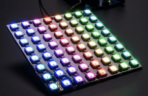
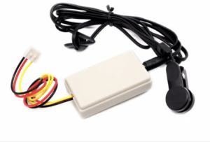
We wanted to use this project to make people around us more aware of their health. It just so happened that we were browsing the equipment website and came across the temperature sensor and the heartbeat sensor, so we started thinking about whether we could use these two sensors to make our project. But we went to the equipment room and asked about it, and they told us they didn’t have the temperature sensor we wanted, so we opted to just use the heartbeat sensor. But how to create interaction between our project and our testers is what we were thinking about, and we saw the neopixel led light on the web, so we decided to combine it with the heartbeat sensor to visualize people’s heartbeats. We planned to use the image in the shape of a heart to represent the heartbeat, and the heart on the neopixel would flash once for each heartbeat, so that people could clearly feel their heart rate.
While thinking about this, we felt that our project would definitely be less accurate and intuitive than the professional medical report like an EKG. So there was no point in just doing the health theme. Then, we started to think about the special features of our project, and we thought we would visualize the heartbeat more tangibly, and we also planned that the hearts on the neopixel screen could be in different colors when the heartbeat speed was different.
So we realized that our project was actually bringing the heartbeat (a kind of physiological activity), which people usually ignore, to our life in a concrete way. Our body never lies to us, which means our heartbeat doesn’t lie as well. In fact, the speed of our heartbeat changes at all times depending on different situations. Sometimes because of our moods, sometimes because of our physical activities, our heartbeat can actually reflect many, many things that we overlook.
The point of our project is to let people feel their inner authentic feelings by actually seeing the changes in their heart rate and feeling the changes in their emotional or physical state. Your heart would never lie, so through our project, you can see your “true colors,” which means how you really feel, who you really are. Our project was designed for everybody, everyone can see their own heartbeat and trace their inner activities while using our project.
C. CONCEPTION AND DESIGN:
Considering that what we needed to do was an interactive device, and our original vision was that the user would just wear a heartbeat sensor and then see their heartbeat flashing on the neopixel screen. But we later felt that with such a design, there was too little human interaction with the machine, and the user was only passively receiving information. So we planned to improve our device and we decided to let the user actively start the heartbeat visualization process. So we added a press switch, and we’re going to make a flexible, user-controlled switch out of cardboard (drawing on the experience of the solder switch taught by Professor Minsky in the first recitation class). I will describe the design of this interactive switch in detail later. This switch let the user decide by themselves when to start their heartbeat visualization journey. We initially designed the hearts with only one color, but to add further interaction to the user’s experience, so we wanted to show them their heart rate more visibly, so we decided to add the color variable. We decided to program the flashing hearts with different colors, and the difference in color reflected the difference in the speed of their heartbeat.
As for what materials and forms to use to represent this interaction, I actually mentioned it above. We used heartbeat sensor to track the heartbeat, neopixel light screen to visualize the heartbeat, and cardboard to create the basic shape of the project and control its switch. In fact, we have thought about using other sensors before, such as sound sensors, but we feel that the heart rate is more easily ignored by us, and is also more truly, unconsciously responsive to our physiological and psychological state. So in the end, we chose the combination of heartbeat sensor and neopixel.

D. FABRICATION AND PRODUCTION:
- The Mechanism Part:
I was mainly responsible for this mechanical engineering part, I was responsible for making the whole appearance of the device and the cardboard button. I also needed to connect the neopixel to the whole project to make our project look integrated. I initially thought of folding the neopixel device around a cylinder of cardboard to form a ring, and here’s my original sketch: 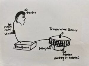
But then we felt that this would instead make it difficult for the user to see the flashing hearts on the screen, so we still planned to have the neopixel screen placed straight up.
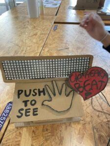
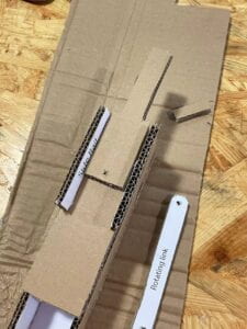
I used cardboard to make a button as the main part of this project. In fact, the design of this switch was very smart and not difficult at all. I folded a piece of cardboard twice, and because of the sturdiness of the cardboard itself, it will spring back to its original shape after being pressed, just in the right way to become a button.
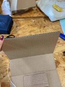
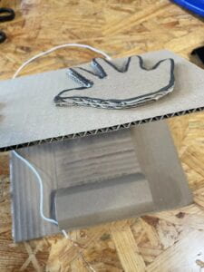
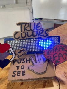
I put another palm made of cardboard on the button as a clear instruction, and I also wrote a line around this palm with the instruction “Push to see your heartbeat,” so that users know exactly what they need to do.
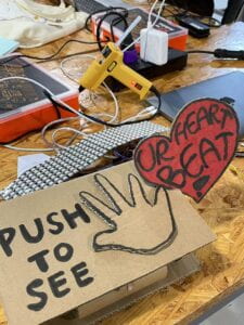
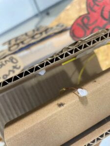
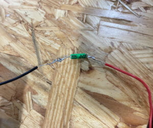
How did I get this cardboard to connect to the Arduino circuit? It was actually quite simple, as taught in the first recitation class, using two wires. I used hot melt glue to fix them on the cardboard, and when the button was pressed, the metal of the two wires collided and the circuit was connected.
Then I fixed the neopixel screen on top of this cardboard button, so that the whole project looked like a whole again and was clearly visible to the user.
- The Wiring and Coding:
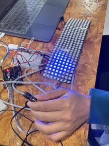
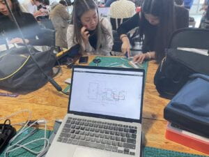
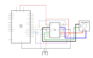
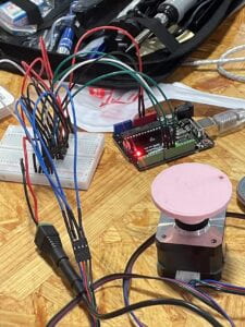
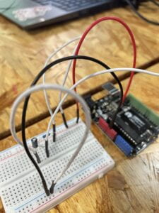
Sid and I designed the wiring together, and we connected neopixel and the heartbeat sensor to the breadboard and the Arduino. The wiring was not very hard, since we didn’t apply many elements. The whole wiring’s like this:
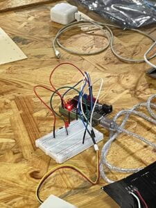
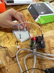
And my partner Sid was in charge of the coding part. At first, he coded two red hearts, which would appear separately depending on the frequency of the heartbeat. But we felt that this was too monotonous for the whole picture. So we decided to change the red hearts that appear alternately at the two ends of the screen to moving hearts that flash from the left side of the screen to the right side of the screen, which would be a little more dynamic. Then later, after we decided to add a different color element, we decided to set some numerical dividers for the heartbeat speed with code. When the heartbeat speed is below a certain value, the displayed heart is blue. And when it is higher than that value, the hearts are red and purple.
As for some coding details, I found it a bit hard for me. But Sid worked with me and he taught me how to code and how it worked. And now I understood the code very well too.
So basically the whole process was like this:
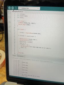
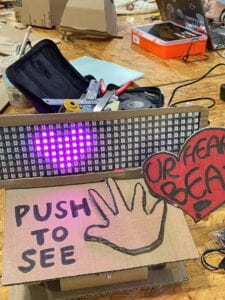
Since the output of the heartbeat sensor is a digital signal, we initially tested its functionality with a simple LED before moving on to the coding portion. After determining it, we sought to determine the beats per minute. To put this into practice, we calculated the interval between two heartbeat signals using the millis() function, and then we used math to calculate how many heartbeats would occur in a minute if each beat lasted the same amount of time as the interval between two beats. As for the Neopixel coding part, Sid discovered some code that produced simple patterns and then modified it to produce a heart. The heart would then move with each beat utilizing for loops and a variety of patterns, repeating as long as a signal from the heartbeat monitor was provided. The color of the hearts was the next thing we wanted to adopt.At first, there were only pre-selected colors, but subsequently, we decided to alter the color of the hearts based on how quickly they beat. We converted the range of a person’s heartbeat to the Neopixel’s color range of 0–255 using the map() method. The hue of the heart changes depending on how quickly or slowly the heart beats, with red being more prevalent and blue being more prevalent. Finally, we added the cardboard button to activate the display.
- User testing and the adjustment we made:
During the User Testing session, the overall feedback on our project has been quite good. We would ask them to check their pulse and they would find that the frequency at which the heart flashes appeared was indeed the exact frequency of their heartbeat. They would also slow down their heartbeat by taking deep breaths, or perform jumping movements to make their heartbeat speed up instantly, and in the process they would actively interact with the device to observe the change in color of the hearts on the Neopixel screen. Here are some videos:
They also made a lot of useful suggestions, such as the fact that although the colors of the hearts on the Neopixel screen were changing, they couldn’t get a very intuitive sense of what the different colors meant, so they suggested that we add an indicator sign. And some people suggested that as well as visualizing the speed of the heartbeat, it could also be displayed through sound, so we later added a buzzer that sounds according to the frequency of the heartbeat.
The color instruction sign: 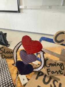
The project’s final format is like this: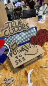
A video showing the whole process:
E. CONCLUSIONS:
The goal of our project is to allow users to see and hear their own heartbeat and actively pay attention to their own heartbeat and mental and physical state through the interaction between the device we design and the user. We hope that through our device, users will begin to think about how their own bodies and their heartbeats reflect their mental and physical states.
“Your heartbeat doesn’t lie.” The interactivity of this device lies in the fact that users consciously wear a heartbeat sensor as well as actively choose to start the procedure, and more importantly, people will actively change their heart rate through some actions, and then they will see on the Neopixel screen the color and blinking speed of the heart that changes according to their changing heart rate. From there, they will perceive that their physical or mental activity is actually changing their heartbeat in a tangible way.
I think our program is pretty interactive to a large extent, but I think if we want to do better. We can learn “manipulate conditions” from psychology class, we can create some fixed scenarios (for example, let the user wear headphones to listen to different music,) and the user will unconsciously according to these different scenarios produce heartbeat changes. This way they can feel the change in their heartbeat more intuitively. As well as our buzzer sound is a bit small and monotonous, our project would also be better if we could further adjust this sound that imitates a heartbeat.
F. ANNEX:
pictures and videos:
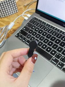


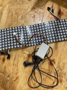


The Code:
#include <Adafruit_NeoPixel.h>
#include <Adafruit_GFX.h>
#include <Adafruit_NeoMatrix.h>
#include “pitches.h”
#define FACTORYRESET_ENABLE 1
#define PIN 6
int melody[] = {
NOTE_C4
};
int noteDurations[] = {
4
};
int pushButton = 2;
int pushButton2 = 9;
int previousState = LOW;
int heartCount = 1;
int c;
long startTime;
float endTime;
float heartRate;
bool test;
bool turnOn = false;
Adafruit_NeoMatrix matrix = Adafruit_NeoMatrix(32, 8, PIN,
NEO_MATRIX_TOP + NEO_MATRIX_LEFT +
NEO_MATRIX_COLUMNS + NEO_MATRIX_ZIGZAG,
NEO_GRB + NEO_KHZ800);
// the setup function runs once when you press reset or power the board
void setup() {
// initialize digital pin LED_BUILTIN as an output.
pinMode(3, OUTPUT);
pinMode(pushButton2, INPUT);
Serial.begin(9600);
pinMode(pushButton, INPUT);
matrix.begin();
matrix.setBrightness(100);
matrix.fillScreen(0);
matrix.show(); // This sends the updated pixel colors to the hardware.
}
// the loop function runs over and over again forever
void loop() {
int pushButtonState = digitalRead(pushButton2);
int buttonState = digitalRead(pushButton);
if (pushButtonState == HIGH) {
turnOn = true;
}
if (previousState != buttonState && turnOn == HIGH) {
digitalWrite(3, buttonState);
previousState = buttonState;
if (buttonState == HIGH && test != true) {
for (int thisNote = 0; thisNote < 1; thisNote++) {
// to calculate the note duration, take one second divided by the note type.
//e.g. quarter note = 1000 / 4, eighth note = 1000/8, etc.
int noteDuration = 1000 / noteDurations[thisNote];
tone(8, melody[thisNote], noteDuration);
// to distinguish the notes, set a minimum time between them.
// the note’s duration + 30% seems to work well:
int pauseBetweenNotes = noteDuration * 0.40;
delay(pauseBetweenNotes);
// stop the tone playing:
noTone(8);
}
c = map(heartRate, 60, 130, 0, 255);
if (heartCount == 1) {
matrix.fillScreen(0);
Heart1(matrix.Color(c, 0, 255-c));
matrix.show();
heartCount++;
}
else if (heartCount == 3) {
matrix.fillScreen(0);
Heart3(matrix.Color(c, 0, 255-c));
heartCount++;
}
else if (heartCount == 5) {
matrix.fillScreen(0);
Heart5(matrix.Color(c, 0, 255-c));
heartCount++;
}
else if (heartCount == 7) {
matrix.fillScreen(0);
Heart7(matrix.Color(c, 0, 255-c));
heartCount = 1;
}
else if (heartCount == 2) {
matrix.fillScreen(0);
Heart2(matrix.Color(c, 0, 255-c));
heartCount++;
}
else if (heartCount == 4) {
matrix.fillScreen(0);
Heart4(matrix.Color(c, 0, 255-c));
heartCount++;
}
else if (heartCount == 6) {
matrix.fillScreen(0);
Heart6(matrix.Color(c, 0, 255-c));
heartCount++;
}
matrix.show(); // This sends the updated pixel colors to the hardware.
startTime = millis();
test = true;
}
else if (buttonState == HIGH && test == true) {
for (int thisNote = 0; thisNote < 1; thisNote++) {
// to calculate the note duration, take one second divided by the note type.
//e.g. quarter note = 1000 / 4, eighth note = 1000/8, etc.
int noteDuration = 1000 / noteDurations[thisNote];
tone(8, melody[thisNote], noteDuration);
// to distinguish the notes, set a minimum time between them.
// the note’s duration + 30% seems to work well:
int pauseBetweenNotes = noteDuration * 0.40;
delay(pauseBetweenNotes);
// stop the tone playing:
noTone(8);
}
endTime = millis() – startTime;
heartRate = (1/endTime)*60000;
Serial.println(heartRate, 0);
if (heartCount == 1) {
matrix.fillScreen(0);
Heart1(matrix.Color(c, 0, 255-c));
heartCount++;
}
else if (heartCount == 2) {
matrix.fillScreen(0);
Heart2(matrix.Color(c, 0, 255-c));
heartCount++;
}
else if (heartCount == 4) {
matrix.fillScreen(0);
Heart4(matrix.Color(c, 0, 255-c));
heartCount++;
}
else if (heartCount == 6) {
matrix.fillScreen(0);
Heart6(matrix.Color(c, 0, 255-c));
heartCount++;
}
else if (heartCount == 3) {
matrix.fillScreen(0);
Heart3(matrix.Color(c, 0, 255-c));
heartCount++;
}
else if (heartCount == 5) {
matrix.fillScreen(0);
Heart5(matrix.Color(c, 0, 255-c));
heartCount++;
}
else if (heartCount == 7) {
matrix.fillScreen(0);
Heart7(matrix.Color(c, 0, 255-c));
heartCount = 1;
}
matrix.show(); // This sends the updated pixel colors to the hardware.
test = false;
}
}
}
void Heart1(uint32_t c){
matrix.drawLine(1, 1, 2, 1, c); // x0, y0, x1, y1, color
matrix.drawLine(5, 1, 6, 1, c); // x0, y0, x1, y1, color
matrix.drawLine(0, 2, 7, 2, c); // x0, y0, x1, y1, color
matrix.drawLine(0, 3, 7, 3, c); // x, y, color
matrix.drawLine(1, 4, 6, 4, c); // x0, y0, width, height
matrix.drawLine(2, 5, 5, 5, c); // x0, y0, x1, y1, color
matrix.drawLine(3, 6, 4, 6, c); // x0, y0, x1, y1, color
}
void Heart2(uint32_t c){
matrix.drawLine(5, 1, 6, 1, c); // x0, y0, x1, y1, color
matrix.drawLine(9, 1, 10, 1, c); // x0, y0, x1, y1, color
matrix.drawLine(4, 2, 11, 2, c); // x0, y0, x1, y1, color
matrix.drawLine(4, 3, 11, 3, c); // x, y, color
matrix.drawLine(5, 4, 10, 4, c); // x0, y0, width, height
matrix.drawLine(6, 5, 9, 5, c); // x0, y0, x1, y1, color
matrix.drawLine(7, 6, 8, 6, c); // x0, y0, x1, y1, color
}
void Heart3(uint32_t c){
matrix.drawLine(9, 1, 10, 1, c); // x0, y0, x1, y1, color
matrix.drawLine(13, 1, 14, 1, c); // x0, y0, x1, y1, color
matrix.drawLine(8, 2, 15, 2, c); // x0, y0, x1, y1, color
matrix.drawLine(8, 3, 15, 3, c); // x, y, color
matrix.drawLine(9, 4, 14, 4, c); // x0, y0, width, height
matrix.drawLine(10, 5, 13, 5, c); // x0, y0, x1, y1, color
matrix.drawLine(11, 6, 12, 6, c); // x0, y0, x1, y1, color
}
void Heart4(uint32_t c){
matrix.drawLine(13, 1, 14, 1, c); // x0, y0, x1, y1, color
matrix.drawLine(17, 1, 18, 1, c); // x0, y0, x1, y1, color
matrix.drawLine(12, 2, 19, 2, c); // x0, y0, x1, y1, color
matrix.drawLine(12, 3, 19, 3, c); // x, y, color
matrix.drawLine(13, 4, 18, 4, c); // x0, y0, width, height
matrix.drawLine(14, 5, 17, 5, c); // x0, y0, x1, y1, color
matrix.drawLine(15, 6, 16, 6, c); // x0, y0, x1, y1, color
}
void Heart5(uint32_t c){
matrix.drawLine(17, 1, 18, 1, c); // x0, y0, x1, y1, color
matrix.drawLine(21, 1, 22, 1, c); // x0, y0, x1, y1, color
matrix.drawLine(16, 2, 23, 2, c); // x0, y0, x1, y1, color
matrix.drawLine(16, 3, 23, 3, c); // x, y, color
matrix.drawLine(17, 4, 22, 4, c); // x0, y0, width, height
matrix.drawLine(18, 5, 21, 5, c); // x0, y0, x1, y1, color
matrix.drawLine(19, 6, 20, 6, c); // x0, y0, x1, y1, color
}
void Heart6(uint32_t c){
matrix.drawLine(21, 1, 22, 1, c); // x0, y0, x1, y1, color
matrix.drawLine(25, 1, 26, 1, c); // x0, y0, x1, y1, color
matrix.drawLine(20, 2, 27, 2, c); // x0, y0, x1, y1, color
matrix.drawLine(20, 3, 27, 3, c); // x, y, color
matrix.drawLine(21, 4, 26, 4, c); // x0, y0, width, height
matrix.drawLine(22, 5, 25, 5, c); // x0, y0, x1, y1, color
matrix.drawLine(23, 6, 24, 6, c); // x0, y0, x1, y1, color
}
void Heart7(uint32_t c){
matrix.drawLine(25, 1, 26, 1, c); // x0, y0, x1, y1, color
matrix.drawLine(29, 1, 30, 1, c); // x0, y0, x1, y1, color
matrix.drawLine(24, 2, 31, 2, c); // x0, y0, x1, y1, color
matrix.drawLine(24, 3, 31, 3, c); // x, y, color
matrix.drawLine(25, 4, 30, 4, c); // x0, y0, width, height
matrix.drawLine(26, 5, 29, 5, c); // x0, y0, x1, y1, color
matrix.drawLine(27, 6, 28, 6, c); // x0, y0, x1, y1, color
}

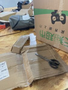
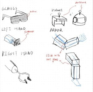 We first found some cardboard in the corner of room 826, and we divided the work.
  Sarah and Smile offered to make the glasses. They measured the width of Smile’s face to make the glasses fit her face perfectly.
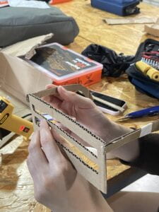
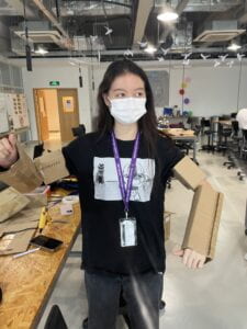
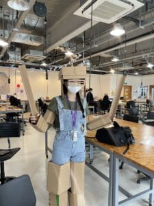
 Chaoyue and I were going to make the arm and leg parts. It wasn’t very hard, but we needed to make several pieces to cover her arms and legs well.
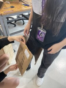
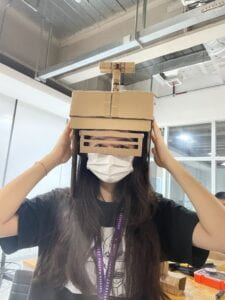
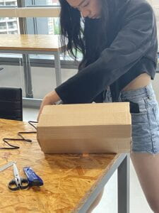 Andy and Jason went to do the helmet part!
 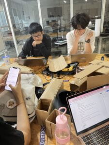 They were seriously thinking about the construction of the helmet…
 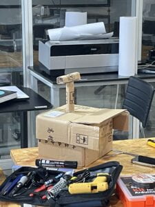 During the robot-making process,
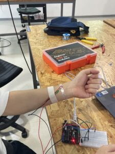 The next step was to wear the circuit, more specifically, to attach the sensor to our arm. And I used tape to put the sensor on Ragnor’s arm.