During the first week of recitation, I paired with Jason to make a circuit!!
At the beginning of the class, we met some of the fellows and learning assistants, and they gave us the mission to make some circuits with several materials. So basically, what we got is a breadboard, a buzzer, a push-button switch, some resistors, a variable resistor, several jumper cables, a power, and 2 LED lights.
These are what we got: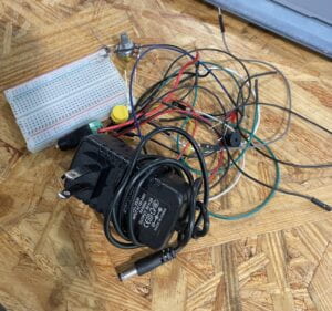
The first circuit:
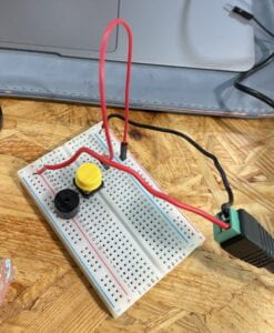
The first thing we did was make a very basic circuit with a switch, a buzzer, a power, and some jump cables. We studied that schematic but failed to operate it. Our main problem was being so confused about the structure of the breadboard. Then we turned to Corina, our learning assistant, and she used a disassembled breadboard to show us its internal structure, and how things worked with the breadboard. After understanding the principles involved, we started our own attempt again.
We connected the red line of the power to the positive side of the breadboard and the black one to the negative. Then install the buzzer and switch. The process wasn’t very complicated, but after we plugged in the power, the buzzer couldn’t be controlled by the switch. So something went wrong, and we found it was about how we connected the switch. Corina showed us a picture of the push-button switch and told us we should connect the A and D poles of the switch, instead of connecting the A and B poles. We then tried to plug the jump cable into the line where the D pole was, and it finally worked.
The Soldering:
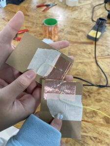
After working out the first circuit, we went to the soldering workshop taught by Professor Minsky. Professor showed us how to use the machine to solder. And taught us how to use cardboard, tape, copper tape, and wire to make a paddle buttom step by step. The professor taught very carefully, other steps are also very simple, the only difficulty is the very step of soldering. It was about controlling and needing practice. My partner Jason tried first, and he did it pretty well, but the soldering wasn’t very strong. Then I started soldering my wire, learning from Jason’s experience, so I melted more material, and it was stronger.
The second circuit:
With the experience of making the first circuit, the second circuit was not a difficult task for us anymore. We changed the position of the switch and buzzer a bit to make there’s a bigger space for other materials. Then we added a resistor and a LED to the circuit, but the first attempt only succeeded half. Because our LED light was not connected to the switch, so it was always on. We adjusted the position of the jump cable, then the light was finally able to be controlled by the switch.
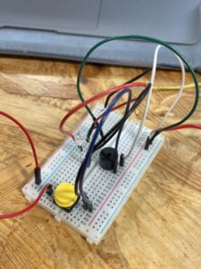
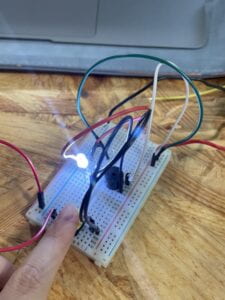
The final circuit:
Only 10 minutes left, and we had one last circuit, which was the most complicated one to do. But we already had a lot of experience and had mastered the principle of this circuit, so we just needed to follow the same pattern. But how to connect the variable resistor to the breadboard was a problem for us, there were 3 outputs of the resistor, and it confused us about which output to connect the cable. Then the fellow Iris told us to use the cables to connect the outputs which were the closest. One was to lead and one was to resist. Also, our classmate Sid provided some assistance with us, so we finished the final circuit very fast and smoothly. He helped me take a video as well. The brightness of the red LED could be adjusted by moving the variable resistor, and the white LED and buzzer could be controlled by the switch. I felt a sense of accomplishment when I saw that the circuit we had built was working successfully. And last, we replaced the push-button switch with the paddle switch we made in the soldering workshop!
Here’s the final videos:
Questions:
Q1: What is the function of the resistor R1?
A1: R1 is mainly used to stabilize the current and voltage in the circuit. Since the battery provides more current and voltage than the LED1 can carry, so a resistor is needed to avoid a short circuit when it’s connected to a LED.
Q2: Looking at the following circuit, draw its diagram by yourself.
A2: 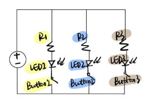
Q3: After reading The Art of Interactive Design, in what way do you think that the circuit you built today includes interactivity? Which degree of interactivity does it possess? Please explain your answer.
A3: I think there’s interactivity between this circuit and us, and also between the different elements in the circuit. Take the first and simplest circuit for example, after we built the circuit, when we press the switch, the circuit started to operate, which means it started the “thinking” step mentioned in the article, then the current passed through the switch and the buzzer, the buzzer sounded, and the whole process of interaction was finished. I feel like the working circuit formed a benign interaction between information and between people and circuits.
Q4: How can Interaction Design and Physical Computing be used to create Interactive Art? You can reference Zack Lieberman’s video or any other artists that you know.
A4: Physical computing and interaction design produce mediums and platforms where people may relate to the digital environment, giving interactive artists the means to change data about human behavior. It may capture the focus of the line of sight and use the eyes as a brush to write and draw, similar to a human-computer interaction tool called Eyewriter introduced by Zack Lieberman, to allow paralyzed people more effectively express their individual requirements and to foster engagement. the making and improvement of art. Interaction design and physical computing applications broaden usable human tools, enabling people to produce more vibrant art.
Reference
O’Sullivan, Dan, and Tom Igoe. Physical Computing. Course, 2004.