This week you will work in pairs to connect a wireless circuit using sensors and actuators.
Each group will use:
Equipment |
Qty |
Pic |
Notes |
| Arduino Lilypad USB | 2 |  |
The LilyPad Arduino USB is a microcontroller board based on the ATmega32u4. It has 9 digital input/output pins (of which 4 can be used as PWM outputs and 4 as analog inputs), an 8 MHz resonator, a micro USB connection, a JST connector for a 3.7V LiPo battery, and a reset button. It contains everything needed to support the microcontroller; simply connect it to a computer with a USB cable or power it with a battery to get started. |
| sensor | 1 | 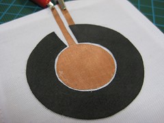 |
Ideally the one you made in the previous class. |
| 10K ohm resistor | 1 |  |
|
| 220 ohm resistor | 1 |  |
|
| LED | 1 | 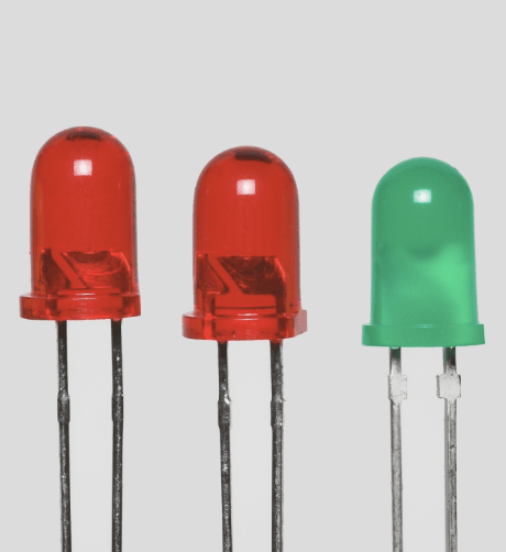 |
|
| X-Bees | 2 | 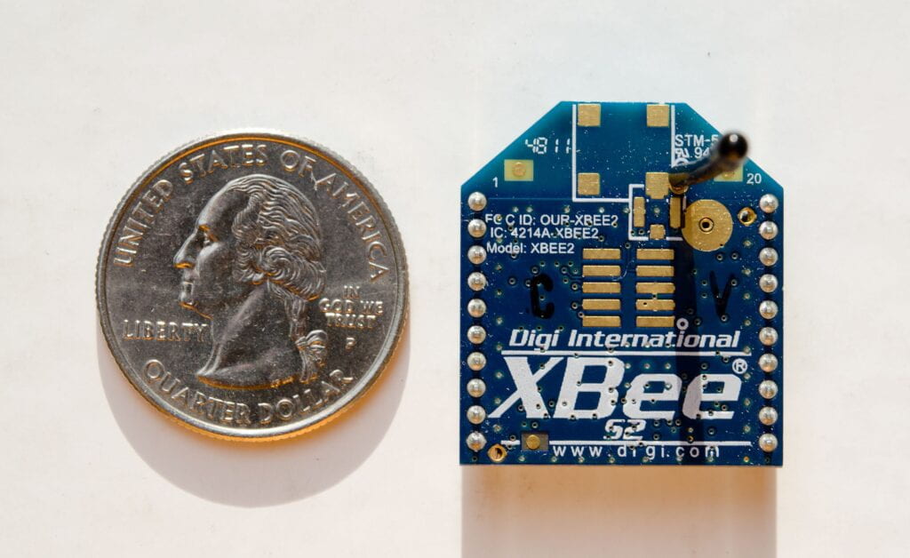 |
For the wireless communication you will use X-Bees. XBees is a brand of radio transceiver that includes many types: point-to-point, 802.15.4, mesh networking ZigBee, and Internet-ready WiFi to name a few. There are many ways in which XBees can be used (in pairs, multiples, or networks, with and without a microcontroller). Today, we will communicate a LilyPad to a computer and two LilyPad together using the most basic setup—XBee 802.15.4 radios in pairs. |
| XBee Adapter | 2 | 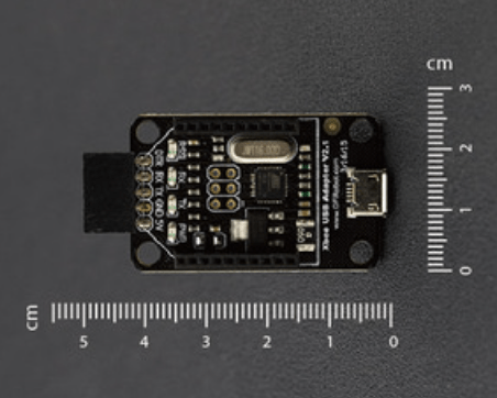 |
The XBee USB Adapter V2 is an update version from DFRobot. It features an Atmega8U2 programmed as a USB-to-serial converter, the same chip found on the Arduino Uno. The Atmega8U2 firmware uses the standard USB COM drivers, and no external driver is needed. However, on Windows, a .inf file is required. It’s compatible with all the products using XBee socket. It provides a faster and stable wireless communication for your projects. |
| Battery | 2 | TBD | |
| Neopixels | 1 | 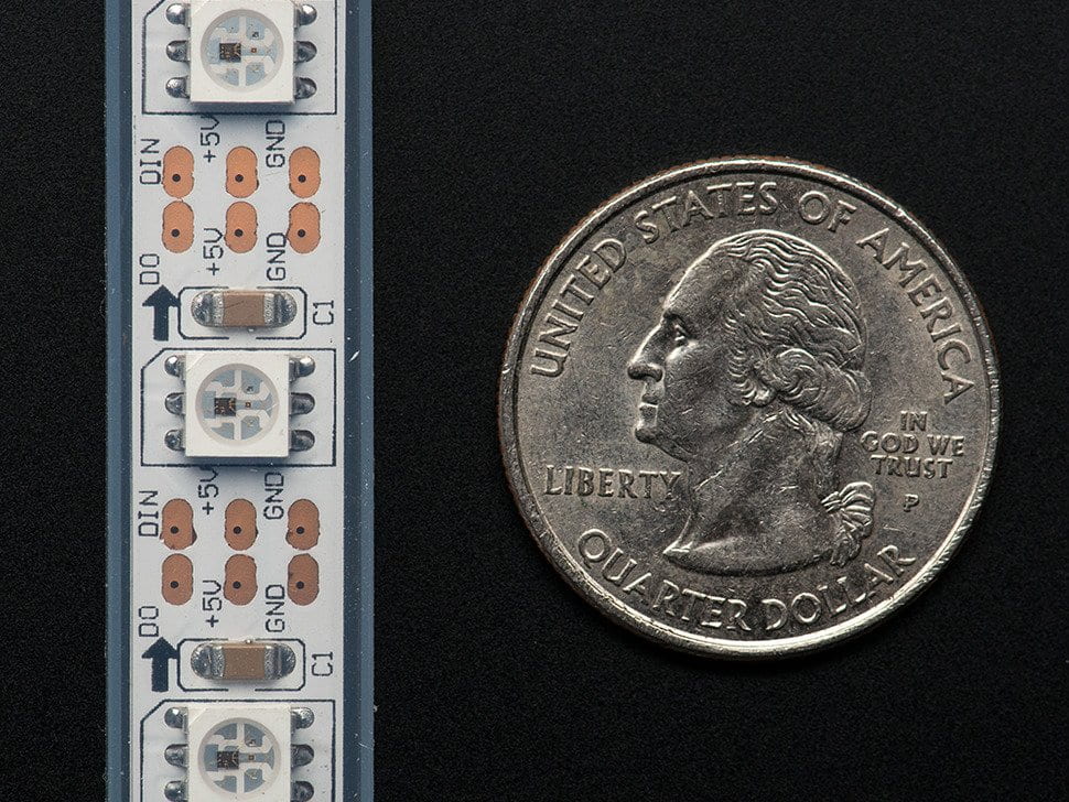 |
You will be using FastLED Library.(or Neopixel Library if you know how to use that one) |
| Breadboard | 1 |  |
This is just for prototyping. If you were sewing the sensor on the wearable , you can use conductive thread or wires as we have been doing it in the previous exercises. |
| Micro USB cable | 1 |  |
This is a cable to connect the XBees and the Lilypads to the computer |
| Aligator Clips |  |
When working with unusual non-header-friendly surfaces, these handy cables will be your best friends! | |
| XCTU | 1 | Software | XCTU is a free, multi-platform application compatible with Windows, MacOS and Linux. Download and install XCTU before you start.(direct links to download for mac and for PC) |
| Software Serial | 1 | Arduino Library |
The SoftwareSerial library allows serial communication on other digital pins of an Arduino board.
|
The next steps are showing what you will normally do if you are working alone and you have to set up a circuit to transmit information and another to receive it. Today you will only be working on connecting a LilyPad to receive data from another Lilypad via wireless communication. Then you will use this data to control an output connected to a Lilypad, and after that to control something with Processing.
1.1. CONNECTING
1.2. PROGRAMMING XBEE A
1.3. PROGRAMMING XBEE B
2. COMMUNICATION FROM LILYPAD A TO LILYPAD B
2.1. PROGRAMMING THE LILYPAD A
2.2. CONNECTING THE LILYPAD A TO THE XBEE A
2.3. PROGRAMMING THE LILYPAD B
2.4. CONNECTING THE LILYPAD B TO THE XBEE B
3. COMMUNICATION FROM ONE LILYPAD TO PROCESSING
3.1. PROGRAMMING THE LILYPAD A
3.2. CONNECTING THE LILYPAD A TO THE XBEE
3.3. PROCESSING CODE
3.3. CONNECTING XBEE B TO PROCESSING
1. Programming the Xbees:
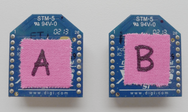
Use some tape and a marker to label the XBees so that it is easy to identify which is which. Here you can see that the XBees have been labeled “A” and “B” for easy reference
1.1. Connecting
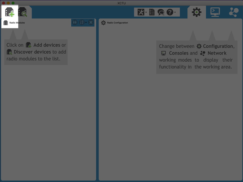
Connect your Xbee to the computer using the LilyPad XBee and the FTDI, then set the configuration in XCTU and then press “Add devices”
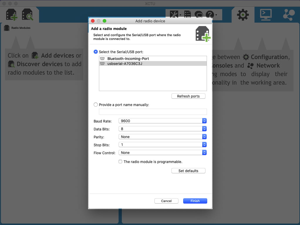
Select the Serial/USB port:
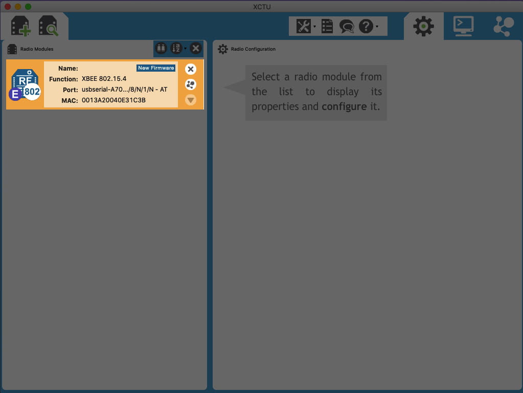
Click on the device found to select and see its properties.
1.2. Programming Xbee A
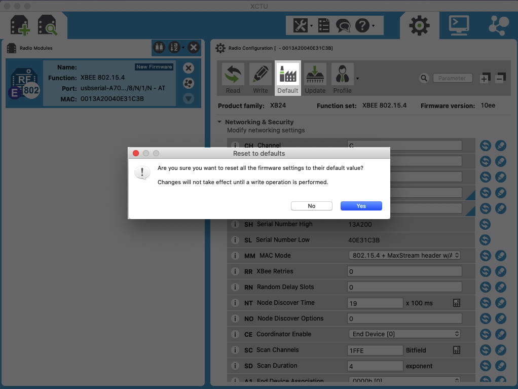
Select “Default” to reset all the firmware settings to their default value.
Network ID (ID), Destination, Source
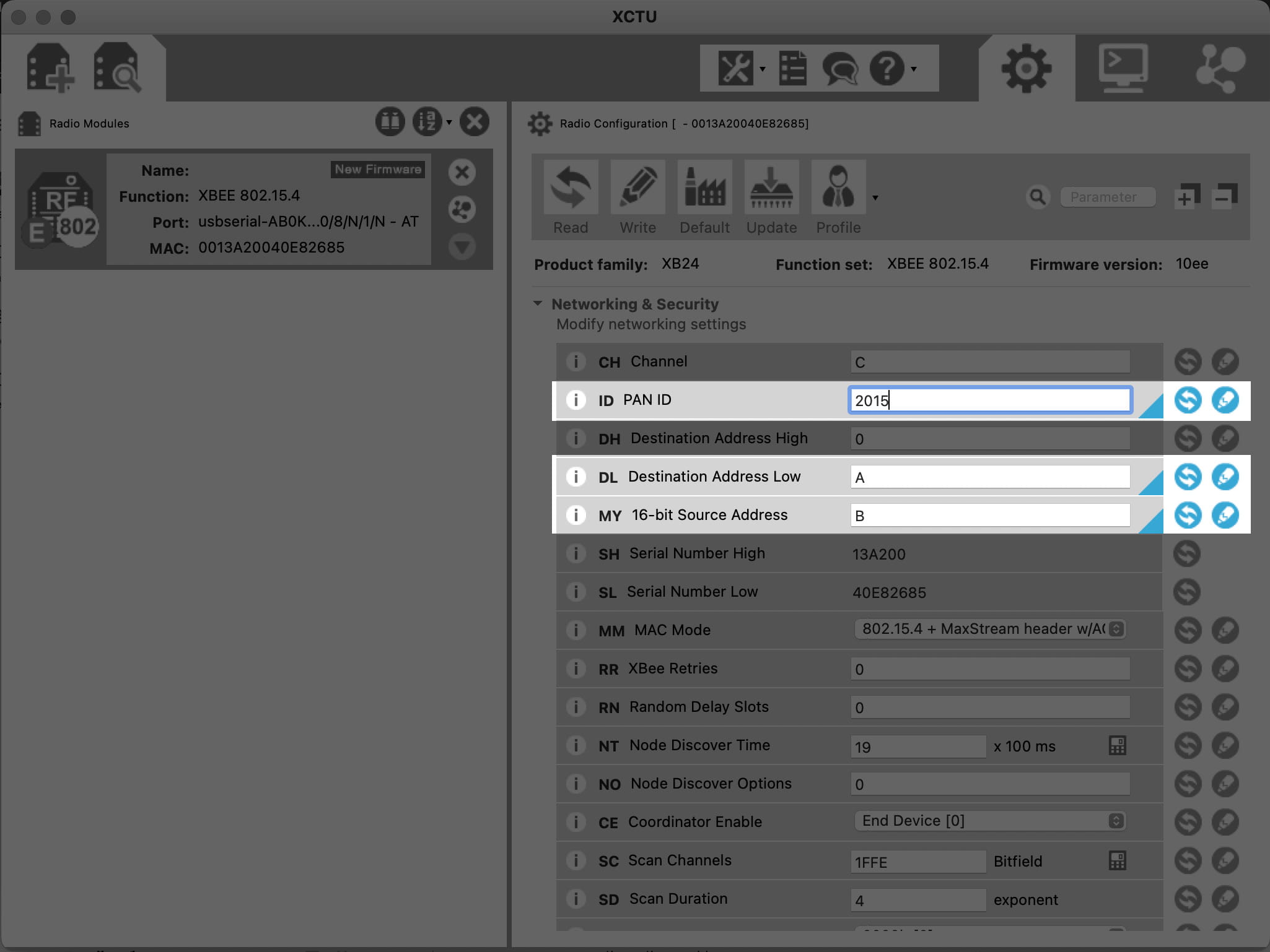
Begin by coming up with a unique network ID number. Think of your favorite number between 0 and 65535, consult your friends and neighbors to make sure your favorite isn’t their favorite, then convert it to hexadecimal. Or if you don’t want to put that much effort into it, use a random value like 2015.
Type your 16-bit network ID into the white text box next to PAN ID.
Next you will set up Xbee A, only changing the values of Destination and Source, like here:
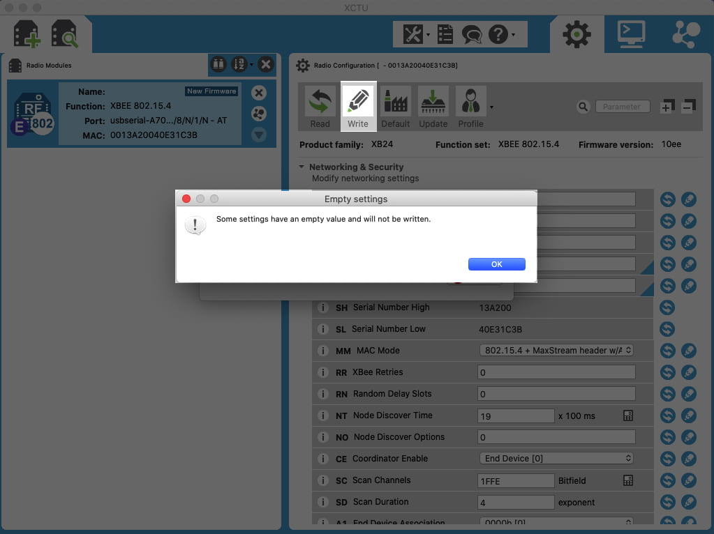
Now press “Write” to save the values:
1.3. Programming Xbee B
Network ID (ID), Destination, Source
Make sure your PAN ID is exactly the same you set up previously!
Disconnect Xbee A and repeat the steps for connecting and programming Xbee A. After returning the settings of Xbee B to the default values, write the new values of Destination and Source, like here:
Finally press “Write” to save the values:
Now that the XBees are configured, they are ready to communicate with each other.
2. COMMUNICATION FROM LILYPAD A TO LILYPAD B
Check out the example code for Serial Communication on Github: SerialCommunicationXBees: ArduinoToArduino
2.1. Programming the LilyPad A
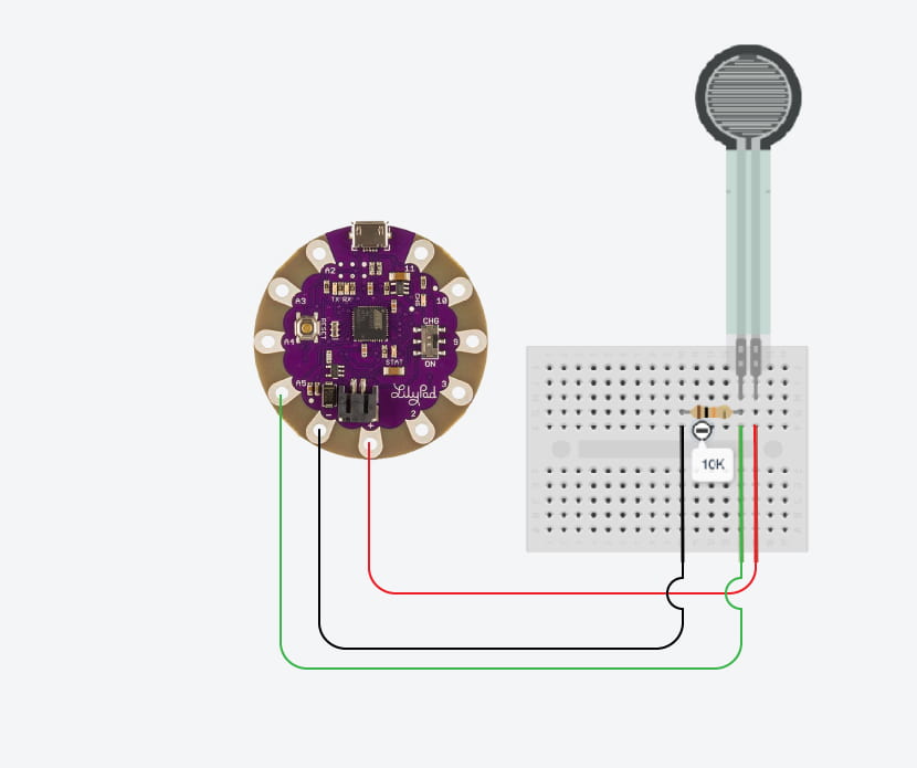
After the Xbees are configured you can upload Arduino sketches to the LilyPad. Connect a sensor using the schematics below:
When you finish, connect your LilyPad to your computer and open Arduino IDE and select “LilyPad Arduino USB” from the Tools > Board menu
Also, make sure the USB port is connected by going to Tools > Port menu.
Read the values from your sensor using the example code: AnalogReadSerial. Remember to change the Analog Pin in the code for the one you are using to connect the sensor.
To send values through the XBees you can use the same format as the code for sending values from Arduino to Processing. Remember Serial Communication from Interaction Lab?. Here you can see the example code you can use for projects like this: IF_serial_Arduino_to_XBEE . But because you are only sending one value today you can just use: File/Examples/Basics/AnalogReadSerial and send it to the LilyPad. Open the Serial Monitor and check that your sensor is working properly.
2.2. Connecting the Lilypad A to the XBee A
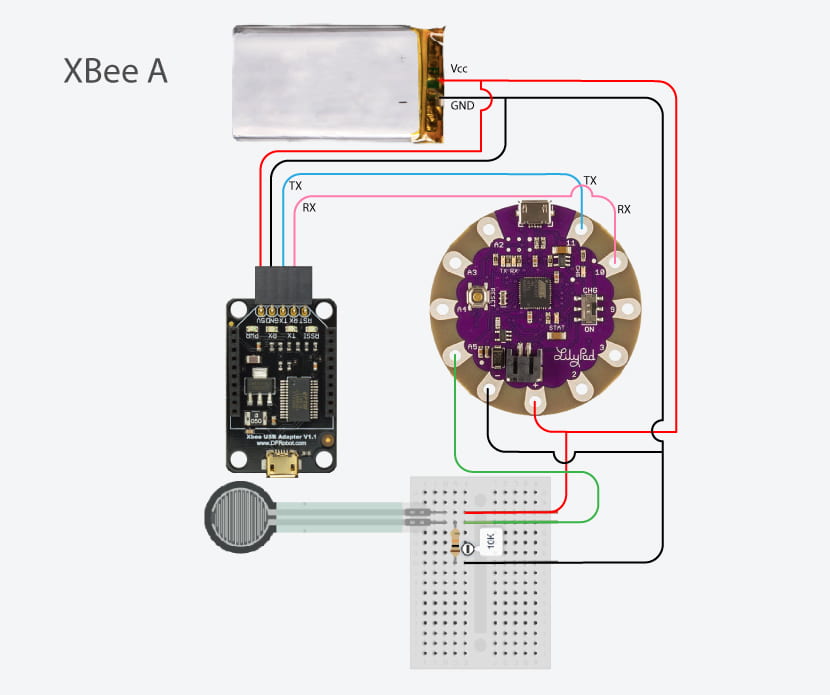
Follow the next diagram to connect your Lilypad with the XBee A.
Usually you will communicate these devices through the TX and RX pins that you can find in an Arduino UNO (pin 0 and 1). We don’t have there pins in the lilypad board, but don’t panic! we can use digital pins for this together with the SoftwareSerial library. This library allows serial communication on other digital pins of an Arduino board and we will be using pin 10 and 11 to do this. You will modify your code to send the values through these pins like this:
#include <SoftwareSerial.h>
SoftwareSerial mySerial(10, 11); // RX, TX

// the setup routine runs once when you press reset:
void setup() {
  // initialize serial communication at 9600 bits per second in your serial port:
  mySerial.begin(9600);
}

// the loop routine runs over and over again forever:
void loop() {
  // read the input on analog pin 0:
  int sensorValue = analogRead(A2);
  // print out the value you read in your serial port:
  mySerial.println(sensorValue);
  delay(1);        // delay in between reads for stability
}
View the general example code in Github
After doing this you won’t see the values in the Serial monitor anymore. If you want to make sure the connections is working, after sending the code above, switch TX to pin 10 and RX to pin 11. Now connect the the USB cable to the XBee adapter instead of the Lilypad and open the serial monitor. Is it working? hopefully yes. Now disconnect the USB cable from your computer and switch back RX to pin 10 and TX to pin 11.
2.3. Programming the LilyPad B
To test our circuit we will start by connecting an LED and changing the brightness of this LED with the values received wireless from the sensor.
Connect the LED with a 220 ohm resistor to one of the digital pins of your second Lilypad. Do not use 10 or 11!
#include <SoftwareSerial.h>
SoftwareSerial mySerial(10, 11); // RX, TX
#define NUM_OF_VALUES_FROM_XBEE 1    /** YOU MUST CHANGE THIS ACCORDING TO YOUR PROJECT **/

/** DO NOT REMOVE THESE **/
int tempValue = 0;
int valueIndex = 0;
We will create an array to store the data from Processing.
int xbee_values[NUM_OF_VALUES_FROM_XBEE];
Start the communication using Serial.begin.
Add any line of code as your project needs.
void setup() {
  // Open serial communications and wait for port to open:
  Serial.begin(9600);
  pinMode(9, OUTPUT);
  mySerial.begin(9600);
}
In void loop you must include getSerialData. This function will get the values coming from Processing and will place them into the array “values” that we created at the beginning.
void loop() {
  getSerialData();
}
You will find the function getSerialData below in the code.
Do not change anything here and make sure you have it in your code!
//receive serial data from Processing
void getSerialData() {
  while (mySerial.available()) {
    char c = mySerial.read();
    //switch - case checks the value of the variable in the switch function
    //in this case, the char c, then runs one of the cases that fit the value of the variable
    //for more information, visit the reference page: https://www.arduino.cc/en/Reference/SwitchCase
    switch (c) {
      //if the char c from Processing is a number between 0 and 9
      case '0'...'9':
        //save the value of char c to tempValue
        //but simultaneously rearrange the existing values saved in tempValue
        //for the digits received through char c to remain coherent
        //if this does not make sense and would like to know more, send an email to me!
        tempValue = tempValue * 10 + c - '0';
        break;
      //if the char c from Processing is a comma
      //indicating that the following values of char c is for the next element in the values array
      case ',':
        xbee_values[valueIndex] = tempValue;
        //reset tempValue value
        tempValue = 0;
        //increment valuesIndex by 1
        valueIndex++;
        break;
      //if the char c from Processing is character 'n'
      //which signals that it is the end of data
      case '\n':
        //save the tempValue
        //this will b the last element in the values array
        xbee_values[valueIndex] = tempValue;
        Serial.println(tempValue);
        //reset tempValue and valueIndex values
        //to clear out the values array for the next round of readings from Processing
        tempValue = 0;
        valueIndex = 0;
        break;
    }
  }
}
Now you will need to add the code to control the Neopixles with the value you are getting from the XBees communication. These values are stored in the first value of the array: xbee_values[0]
For example, you have an LED connected to Pin 9 and you want to change the brightness of it. Your code in the loop function should look something like:
void loop() {
  getSerialData();
  xbee_values[0] = constrain(xbee_values[0], 450, 800);
  xbee_values[0] = map(xbee_values[0], 450, 800, 0, 255);
  analogWrite(9, xbee_values[0]);
}
Don’t forget to include pinMode in the setup function!
pinMode(9, OUTPUT);
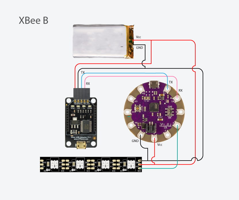
Now that you know how to control a LED, you will now use Neopixels. Follow the next circuit diagram to connect a Neopixel stripe.
Now you can upload a code to control the Neopixels with the values you will be reading from the sensor connected to the other Lilypad through Serial Communication. This is exactly the same that receiving values from Processing to Arduino through the Serial port. So, first you will define the number of values you are receiving from the XBee. This time we are receiving 1 values, so NUM_OF_VALUES_FROM_XBEE is 1.
For controlling Neopixels, you can use the library FastLED. Install the library in your Arduino IDE and then write a code to control the neopixles with the sensor. You can now be creative, maybe the most that you press the sensor, the most LED’s you turn on, or maybe the most that you press, the LEDs change brightness or color. Review the example codes in the FastLED library to get inspired.
2.4. Connecting the Lilypad B to the XBee B
Depending on the XBEE board that you have you should choose one of these diagrams.
3. COMMUNICATION FROM ONE LILYPAD TO PROCESSING
Check out the example code for Serial Communication on Github: SerialCommunicationXBees: ArduinoToProcessing
3.1. Programming the LilyPad A
3.1.1. LilyPad 1: CONNECTING A SENSOR AND SENDING THE VALUES
You already did this. You don’t need to repeat it.
3.2. Connecting the Lilypad A to the XBee A
You already did this. You don’t need to repeat it.
3.3. Processing Code
Start the code by adding the Processing Serial Library
import processing.serial.*;
Define the number of sensor values you will be receiving from the LilyPad A and create an array to store these values. In this example we are receiving only one value, so
NUM_OF_VALUES = 1.
int NUM_OF_VALUES_FROM_XBEE = 1;   /** YOU MUST CHANGE THIS ACCORDING TO YOUR PROJECT **/
int sensorValues[];      /** this array stores values from the Lilypad1 **/
We will create a new String to receive the values from the Lilypad1, this String is the one written like:
sensorValueOne, sensorValueTwo, sensorValueThree
At the end of this line there will be a line feed we will identify and replace the previous String with the new one. We will also split the values when we see a comma.
String myString = null;
Create the serial port
Serial myPort;
Start your setup code as you wish. You must include in the setup a function called setupSerial() that will contain the code to start the communication with the Lilypad1. You will need to set the function up by defining the port number your computer gives to your USB port.
void setup() {
  setupSerial();
}
So go down to the setupSerial() function:
void setupSerial() {
  printArray(Serial.list());
  myPort = new Serial(this, Serial.list()[ PORT_INDEX ], 9600);
  // WARNING!
  // You will definitely get an error here.
  // Change the PORT_INDEX to 0 and try running it again.
  // And then, check the list of the ports,
  // find the port "/dev/cu.usbmodem----" or "/dev/tty.usbmodem----"
  // and replace PORT_INDEX above with the index number of the port.

  myPort.clear();
  // Throw out the first reading,
  // in case we started reading in the middle of a string from the sender.
  myString = myPort.readStringUntil( 10 );  // 10 = '\n'  Linefeed in ASCII
  myString = null;

  sensorValues = new int[NUM_OF_VALUES_FROM_XBEE];
}
Now replace “PORT_INDEX” by a number 0, like this:
myPort = new Serial(this, Serial.list()[0], 9600);
Next, run the code and find in the console the list of ports your computer has. Choose the USB port, for example 1 or 3 in this case:
Change the PORT_INDEX accordingly. In this example your line would be:
myPort = new Serial(this, Serial.list()[3], 9600);
But again, this depends on everyone’s computer, so find your own number.
Now your Processing sketch is connected with the Serial port.
In the draw loop we will use a function called getSerialData() to update the sensor values as they change.
void draw() {
  getSerialData();
}
Remember that the values from the sensors are stored in an array of variables and these variables will be filled with data according to the information we get from the XBee. In this function, we will split the String containing all the sensor values every time there is a comma and we will stop reading the String when we get a line feed (value 10 in ASCII code). We will also print to the console the values we are receiving from the Lilypad through the Xbees’ wireless conection.
Note: If you want to know why we are using trim, check this out.
void getSerialData() {
  while (myPort.available() > 0) {
    myString = myPort.readStringUntil( 10 ); // 10 = '\n'  Linefeed in ASCII
    if (myString != null) {
      String[] serialInArray = split(trim(myString), ",");
      if (serialInArray.length == NUM_OF_VALUES_FROM_XBEE) {
        for (int i=0; i<serialInArray.length; i++) {
          sensorValues[i] = int(serialInArray[i]);
        }
      }
    }
  }
}
Finally, write your code and use the values from the sensors knowing that sensorValues[0] is the value from the first sensor, sensorValues[1] is the value from the second sensor, and sensorValues[2] is the value from the third one. In this case we are only connecting one sensor, so you can only use sensorValues[0]
void draw() {
  getSerialData();
  printArray(sensorValues);

  // use the values like this!
  // sensorValues[0]

  // add your code

  //
}
For example, if you want to draw a circle and change the size of that circle according to the values of the first sensor you are sending from the Lilypad1, your code should look like this:
void draw() {
  getSerialData();
  printArray(sensorValues);

  circle(width/2, height/2, sensorValues[0]);
}
You will probably need to map the values according to what you are doing, for example, if the values you are receiving from the sensor correspond to values from a potentiometer, these values are in a range between 0 and 1023, then the size of the circle will grow outside the canvas. So you might want to map the potentiometer values to the minimum size for the circle to the maximum size you want the circle takes. Then, your code could be something like this:
  float size = map(sensorValues[0], 0, 1023, 0, width);
  circle(width/2, height/2, size);
You can now be creative and write the code for your project as you need.
3.4. Connecting the XBee B to Processing
If you connect the Xbees to Processing you don’t need to connect the Lilypad B with XBee B. You just need to connect XBee B to your computer through the micro USB cable using the Xbee Adapter.
Now you can connect the wireless system to Processing. In this way you could, for example, create a wearable that senses the movements of your body and show a visualization in processing, either with music or graphics.
SUGGESTED READINGS:
- Andrew Brooks ‘Ethical clothing myths and realities’ p207-p232 | Clothing Poverty: The Hidden World of Fast Fashion and Second-Hand Clothes
- Kate Hartman, Make : wearable electronics
- Chapter 9, Wireless
- Sewing for Fashion Designers by Anette Fischer
ASSIGNMENT 4
Document and post to the blog this exercise. Remember to take videos of the circuit working.
How do you imagine you could use what you learned today for a wearable?
