0. Overview
A Laser Cutter is a machine that uses a laser to cut materials. It is usually used in industrial manufacturing application, but it is becoming an increasingly popular tool amongst hobbyists and makers. It can enable you to prototype, fabricate your projects to give them a more polished and finished look.
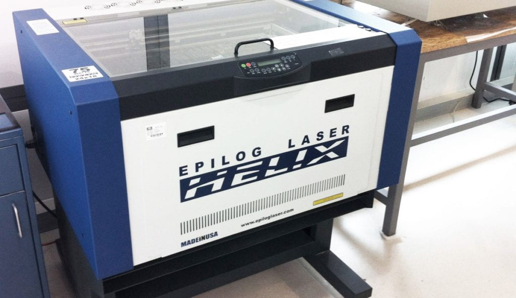
The model at the IMA lab is the Epilog Laser Helix. In this tutorial, students will learn how to design and make adobe illustrator file for laser cut, how to operate the laser machine and basic maintenances about the machine. Students are NOTallowed to use the laser cutter un-supervised due to safety concerns. Instead, they need to make an appointment with IMA faculty or staff, click here.
General procedure for students’ laser cut project:
1.Prepare design file in illustrator, feel free to ask help!
2.Make an appointment, book the available machine.
3.Bring in prepared file and material, find fellows in IMA studio.
4.IMA will provide material to class projects with project supervisor/professor’s permission. Cardboard is recommended for prototyping, IMA has recycled boxes stored in cardboard room.
5.Student MUST be present during the whole cutting process, students are responsible for their own work.
1.How to design and make adobe illustrator file for laser cut
- How to Setup Illustrator Files for the Laser Cutter
- How to Create a Laser Cutter File From an Image
- How to Create Encasing for Project
At the bottom of the page, there is a link that directs you to Adobe Creative Suite video Tutorials.
1.1 How to Setup Illustrator Files for the Laser Cutter.
You can follow the following steps to create your file or follow the template(click to download) we prepared for laser cutting.
Step ONE:
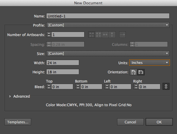
Open Adobe Illustrator, create a new file. To do that, go to File >> New. Be sure to make the width of the page 24 inches and the height 18 inches. This is the size of the cutting bed in the laser cutter. By making your page the same size and ratio as the cutting bed, you can easily estimate the size and placement of your object by referencing the file and also ensure that the making of the object will not be placed outside of the cutting area.
Step TWO:
There are two types of processes that the laser cutter can do: 1) Vector and 2) Raster. Vector cutting means cutting through the material completely to create a separate part from the material. Raster cutting doesn’t cut through the material completely but only carves out the surface of the material.
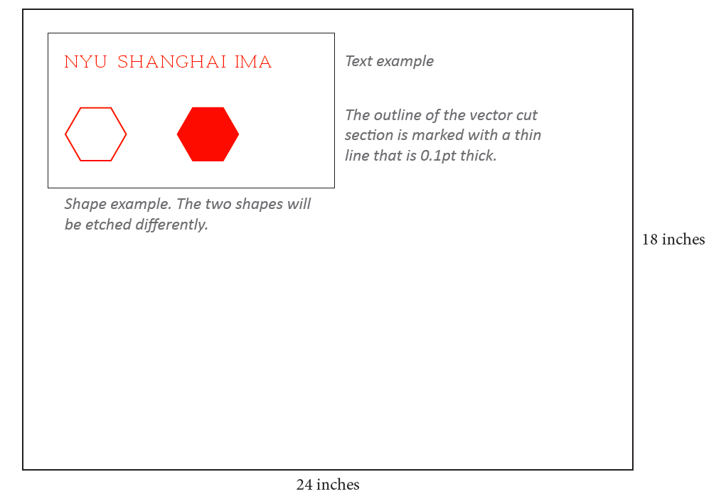
Mark areas for vector cutting by making those lines thinner than the default stroke, instead of 1pt stroke width, make these lines 0.1pt stroke width. To do that, find the stroke setting on the horizontal toolbar on the top of the application:  , then change the setting to 0.1. Make sure the color of the outline is pure black (R: 0, G: 0, B: 0). To change the color setting, double-click the color setting icon
  at the bottom of the toolbar on the left. The white square represents the filling color, the black hollow square represents the outline color. First, double-click the outline square and you will get the following interface:
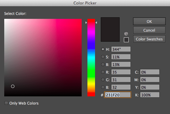
Then change the RGB color settings to 0 and click the “OK” button. Click on the white square to select the fill color:  , select the small square at the bottom right with a red line across it to set the fill color as no fill.
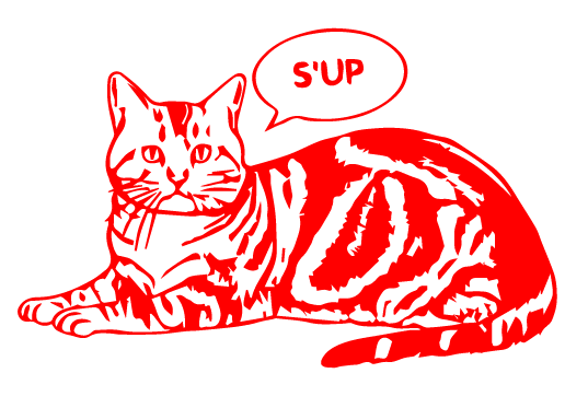
Mark areas for raster cutting by making those areas red (R: 255, G: 0, B:0). Set the outline color to no fill, and set the fill color to red. If you want a solid etch, you must fill the shape you are cutting with red and not only outline it red. If you only set the outline of the shape red, then the machine will only etch an outline. See example below.
NOTE, there must not be any other colors in your file (for instance, white), and all colors must be set strictly to the RGB specifications, otherwise, the file might either not cut or not cut properly when run through the laser cutter.
Step THREE:
After you are done with preparing your Illustrator file, you are ready to cut. Email imafellows@nyu.edu schedule an appointment to cut your file.
1.2. How to Create a Laser Cutter File From an Image
Sometimes, what you want to cut is not composed of simple geometric shapes that you can create in Illustrator. The following steps will teach you how to convert and import more complex images that you either find online or create yourself in software such as Photoshop to Illustrator.
Step ONE:
Whether you downloaded the image online or created it in Photoshop, make sure it’s a large image. that means high resolution. The dpi value marks how high res your image is, usually, images are at 300dpi for print publication, the laser cutter is set at 600dpi for cutting. Your image doesn’t necessarily need to be that high, but depending on what your purpose is, you should be aware of your image resolution. If you are not sure, you can email imafellows@nyu.edu to discuss what is the best option. After you have imported your image into Photoshop or created a new file in Photoshop, you can check the resolution by going to Image >> Image Size at the top of the tool bar. Click to enter the interface and change the resolution to 300 as below:
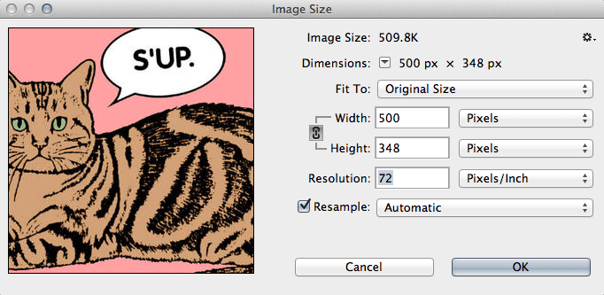
(Usually, internet image’s dpi is set at 72)
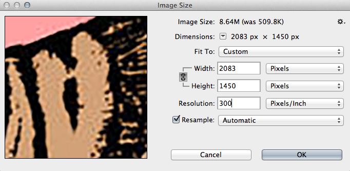
Step TWO:
Desaturate your image first, so that the image is only in black, white and gray. To do this, go to the top of the menu bar and select Image >> Adjustments >> Desaturate.
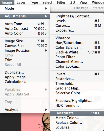
You will get the following result:

This step helps to simplify the image. This is useful because what you need for the laser cutter will only be either an outline or a filled solid mono-color image.
Step THREE:
Now that your image is black and white, you need to adjust it so that there are only two colors (e.g. etch/no-etch or cut/no-cut). To do this, go to Image >> Adjustment >> Posterize at the top of the menu bar.
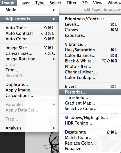
You will be brought to the following window:

The number of levels may be different depending on the image you choose. Change the number of levels into 2, and you will get a clean image that consists of only two colors, black and white.
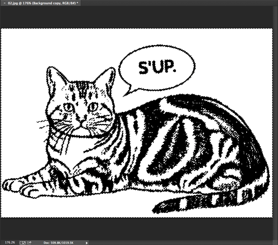
Step FOUR:
Delete the white background of your image and save image as a .png file. .png files support transparent backgrounds, whereas other image formats such as .jpeg or .tiff will automatically convert the background into white upon saving. This is to ensure that you get a clean image of the object you want to etch or cut. First, if there is your image is on the background layer, duplicate your image by right clicking the background layer in the layers window on your right. This is because your background layer is locked.

Select Duplicate Layer in the drop down menu and you will create a layer identical to your background image.
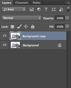
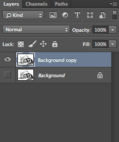
Click on the little eye icon on the background layer to make it invisible and then select the duplicate layer so that following edits to your image will be on that layer.
An easy way to select all white areas is to use the Color Range function in Photoshop. Go to Select >> Color Range in the menu bar above:
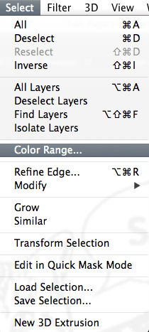
You will arrive at the following window. Select the Highlight option under Select, to only pick out the white areas of your image.
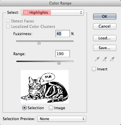
Delete the selected areas to get only your object in black.

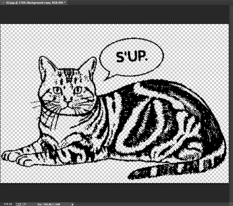
Save image as .png.
Step FIVE:
Import your image into Illustrator by opening up the software and dragging your image into the software’s interface. Select Object >> Image Trace >> Make in the menu bar on the top. (For Adobe Illustrator CS6 and after)
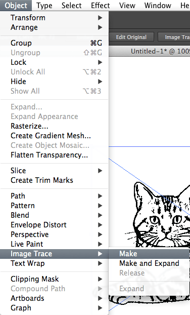
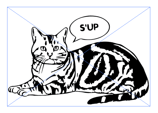
And you will get a vector image. This image has a white background, which the laser cutter will not be able to read
.
To get rid of this background color, and to edit the image, select the image and click on the Image Trace button at the top of the tool bar:  . Then click on the Expand button that appears in the tool bar:
  . You will get the following image:
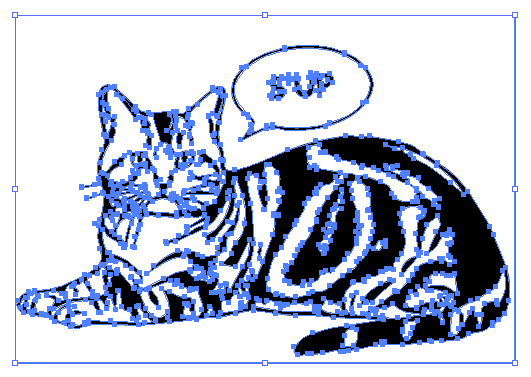
Right click the image and select Ungroup. Now you can delete the background and edit the image for the laser cutter.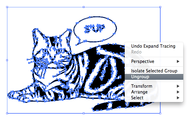
Pull your image to the side of the art board area to make sure that you have deleted all white spaces in the image.
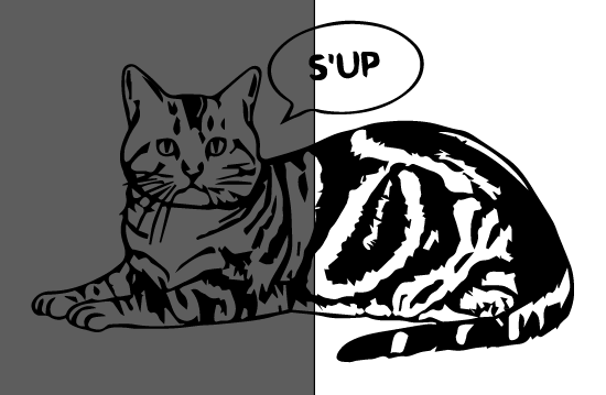
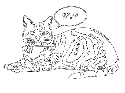
Select all parts of the image, right click and group into one object. Now you can edit the image for cutting or etching.
1.3. How to Create Encasing for Project
Sometimes, it helps to create a box or container for your electronic projects to make them look more finished and complete. There are many online platforms that can make this process easy and accurate. One resource is the MakerCase online tool.
The website allows measurements in both inches and millimeters. You can easily select if you want to generate the box based on its inner or outer measurements, fill in the width, length and height, select if you want flat, finger or T-slot joints and generate laser cutter files for a box. Be sure to measure the thickness of the specific material you are using, so the end result fits well. There is a selection of material thicknesses, you can also fill in a custom thickness. For finger joint or T-slot options, there are sliders that help you determine exactly how the joints would look in terms of density and length. Press the Generate Laser Cutter Plans button, download the file as a .svg file and start editing your box in Illustrator.
If you have trouble editing your file or measuring for specific hole placement, please email imafellows@nyu.edu to schedule an appointment.
For more on software and tools within the Adobe Creative Suite, you can find video tutorials and news at http://tv.adobe.com.







 at the bottom of the toolbar on the left. The white square represents the filling color, the black hollow square represents the outline color. First, double-click the outline square and you will get the following interface:


