Recitation 8: Serial Communication

In this recitation, you will complete the following exercises to send data from Arduino to Processing, and vice versa, using serial communication. You will be using the SerialRecord library.

Task #1:  Make a Processing Etch-A-Sketch
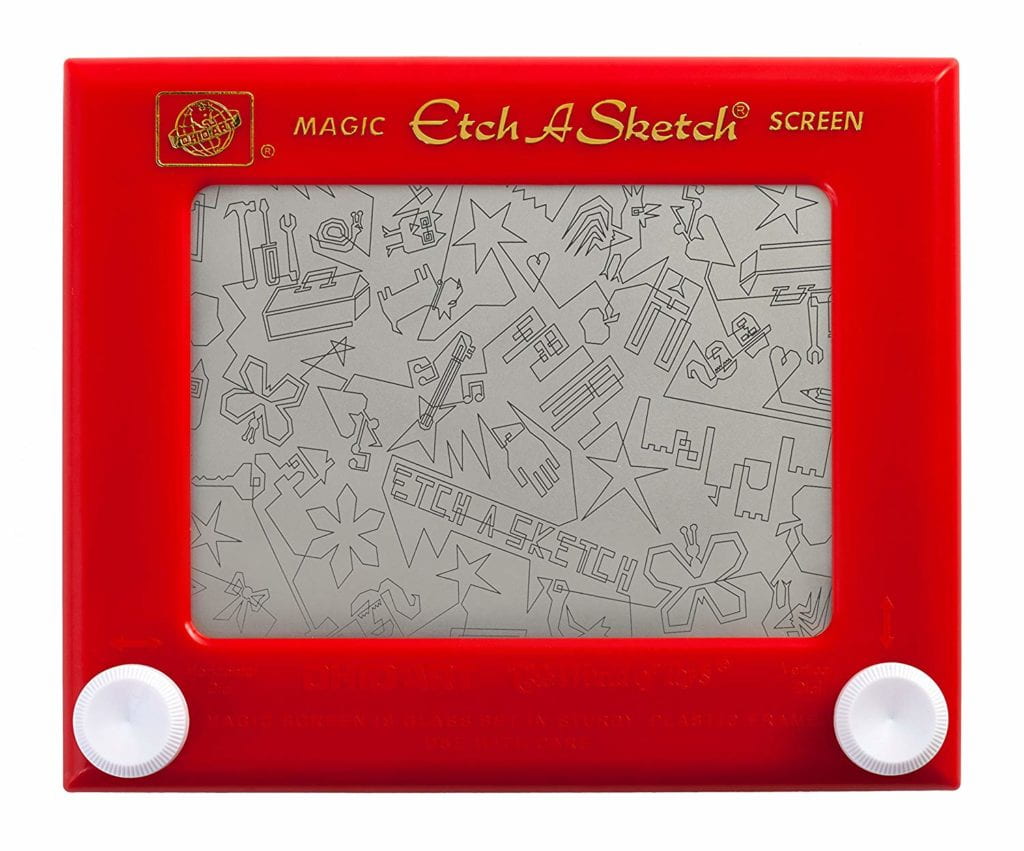
etch-a-sketch
Image from ebay.com

To see how an Etch-A-Sketch works, you can watch a video here.

Arduino example

Working individually, for this exercise, use Arduino to send two analog values to Processing via serial communication. To do this, build a circuit with two potentiometers and write an Arduino sketch that reads their values and sends them serially. (Use SerialRecord example SendMultipleValues as a basis):


processing example


Then, write a Processing sketch that draws a circle and reads those two analog values from Arduino. (Use SerialRecord example ReceiveMultipleValues as a basis). This sketch should modify the circle’s x and y values based on the input from Arduino. Just like an Etch-A-Sketch, one potentiometer should control the circle’s x-axis movement, and the other should control the circle’s y-axis movement. 

Once you have this working with a circle, modify the code to use a line instead (like a real Etch-A-Sketch).  To do this, you will need to keep track of the previous x and y values so that you can draw a line from there to the new x and y positions. You can use this code as a reference.

Task #2:

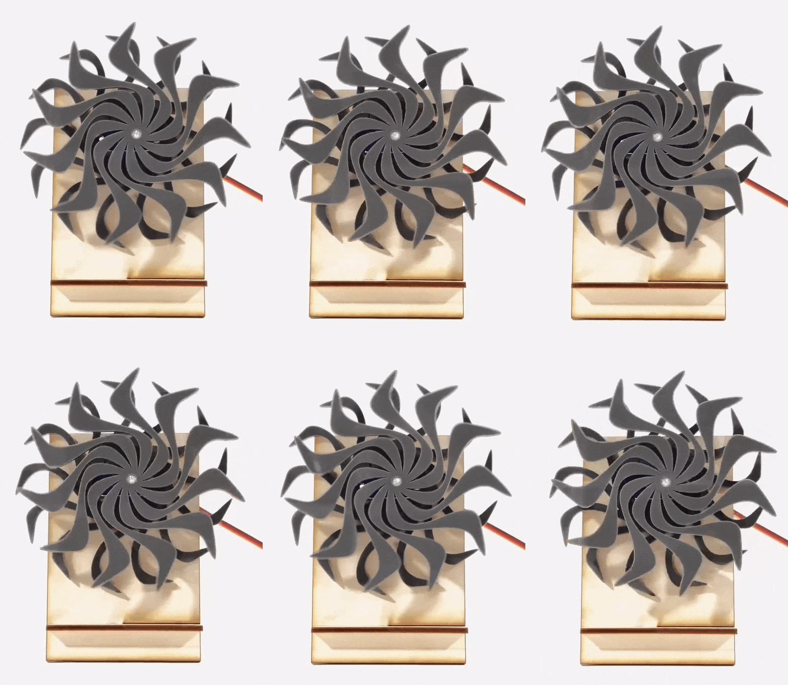
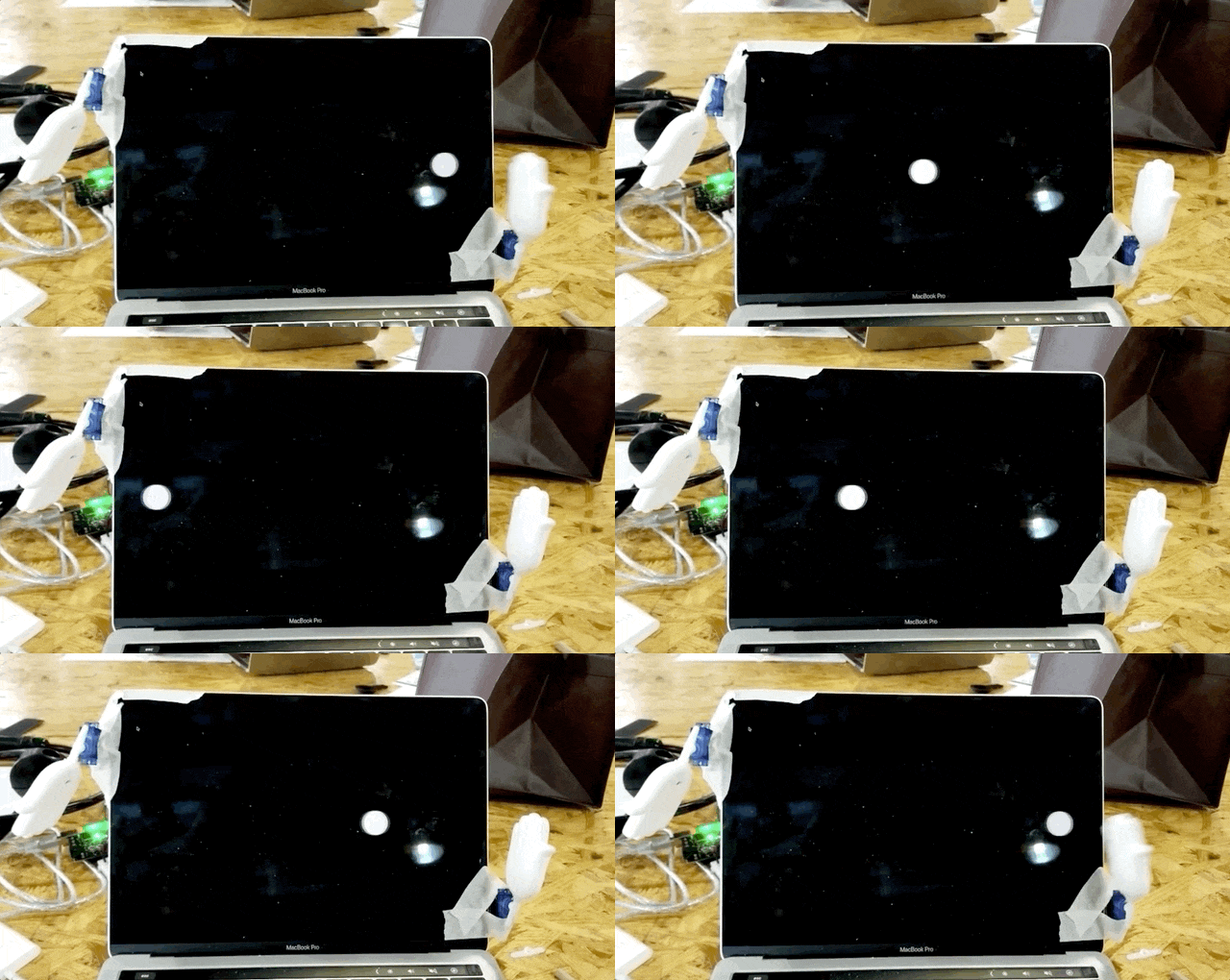
Working as pair, write a Processing sketch in which a ball bounces from left to right on the screen. (You can use the fullScreen() function, instead of size(), to make the Processing window occupy the full dimensions of your screen.) Send values from Processing to Arduino based on the position of the bouncing ball. You can start with the example code in SerialRecord, SendMultipleValues.  These values should somehow give an indication of when the ball hits the edge of the screen. Then, make a circuit with your Arduino and a servo motor. The corresponding Arduino code should read the serial values from Processing and translate them into movements of the servo motor as if it is hitting the ball.  You can use the SerialRecord code as a starter, RecieveMultipleValues. See the animated image below for reference as an example built with two servo motors, you can build it with one instead if you are working individually. 
Documentation

For your blog post, this week include documentation of task #1, task #2, and the Homework.

Task #1 Documentation

  • Document your process for completing the task: (what went well? what was difficult? any surprises?).
  • Include a reflection on the interaction involved.
  • Include a video and a screenshot.
  • Embed your code.
Task #2 Documentation

  • List the name of your pair teammate.
  • Document the process for completing the task: (what went well? what was difficult? any surprises? what was your process of teamwork?).
  • Include a reflection on the interaction involved.
  • Include a video and a screenshot.
  • Embed your code. 

Recitation 9: Digital Fabrication


This week, we will be creating a  kinetic sculpture using digital fabrication tools.
Such sculptures use movement as their basic element to create works of art. 

These self-propelled kinetic wood sculptures by David C. Roy can spin for nearly a day — Colossal
Image: Dimensions by David C. Roy

Step 1: Design

To make your own kinetic sculpture using digital fabrication methods you will first need to design your parts with computer-aided software (CAD).  In this case, you will use cuttle.xyz which is a 2D vector software optimized for laser cutting. Watch the 4 mintue tutorial on cuttle! 

Work together with a partner to build one sculpture. Each one of you will design half of the parts. At the end of the recitation you should end up with something like this:

Step 1.1: Stand design


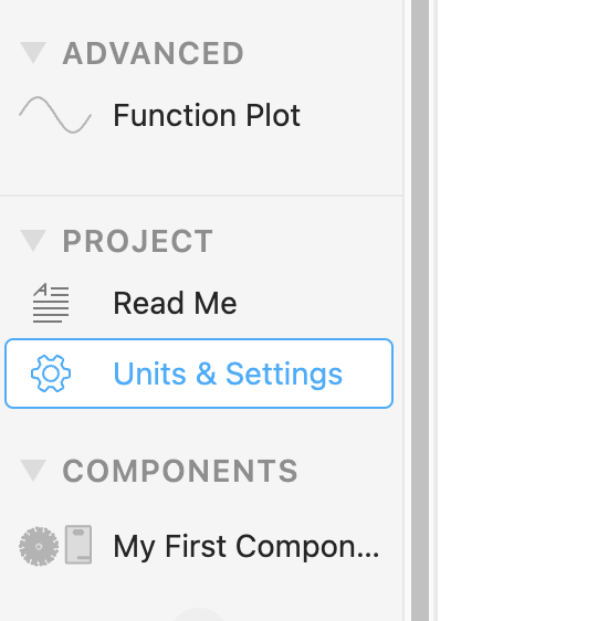
In cuttle, go to Units & Settings to change the inches into millimeters.


Student A   Student B
.

Start by creating a new document and activating the “Grid snapping” option in the toolbar at the top of your canvas. This will help you place components accurately on the grid.

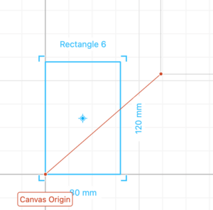
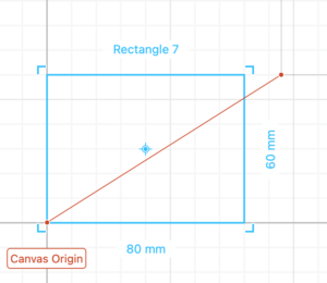
Drag a rectangle a place it in the origin.
Resize to 80 mm wide and 120 mm tall.

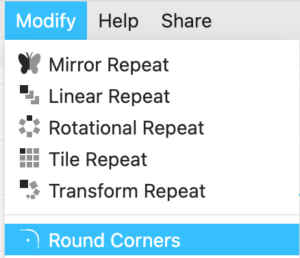
Select the rectangle and add a round corner modifier. Add a 3 mm radius rounded corner.

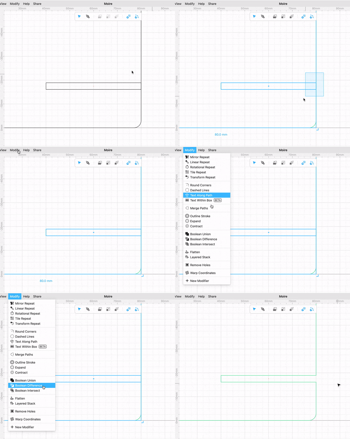
Drag another rectangle size 40 mm wide and 2.8 mm tall (2.8 mm is the thickness of the material we will cut). Place it on the right side edge of the first rectangle you placed and -17.5 mm on the Y axis. This rectangle will create a slot for 2 pieces of wood to intersect with each other and create the stand.

Select both rectangles and perform a “Boolean Difference”. This allows you to subtract one shape from another.

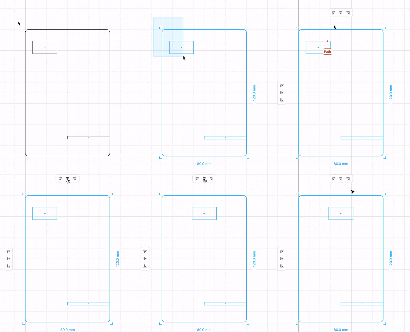
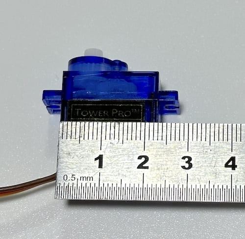
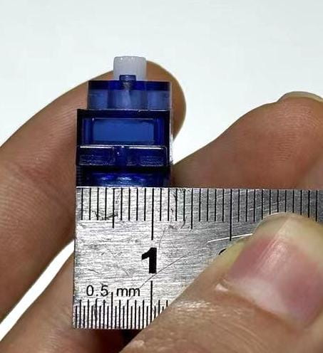
Drag and drop a rectangle based on the servo dimensions measured by your partner.
Select both objects and center-align horizontally as shown in the gif below. Position at Y -100 mm.

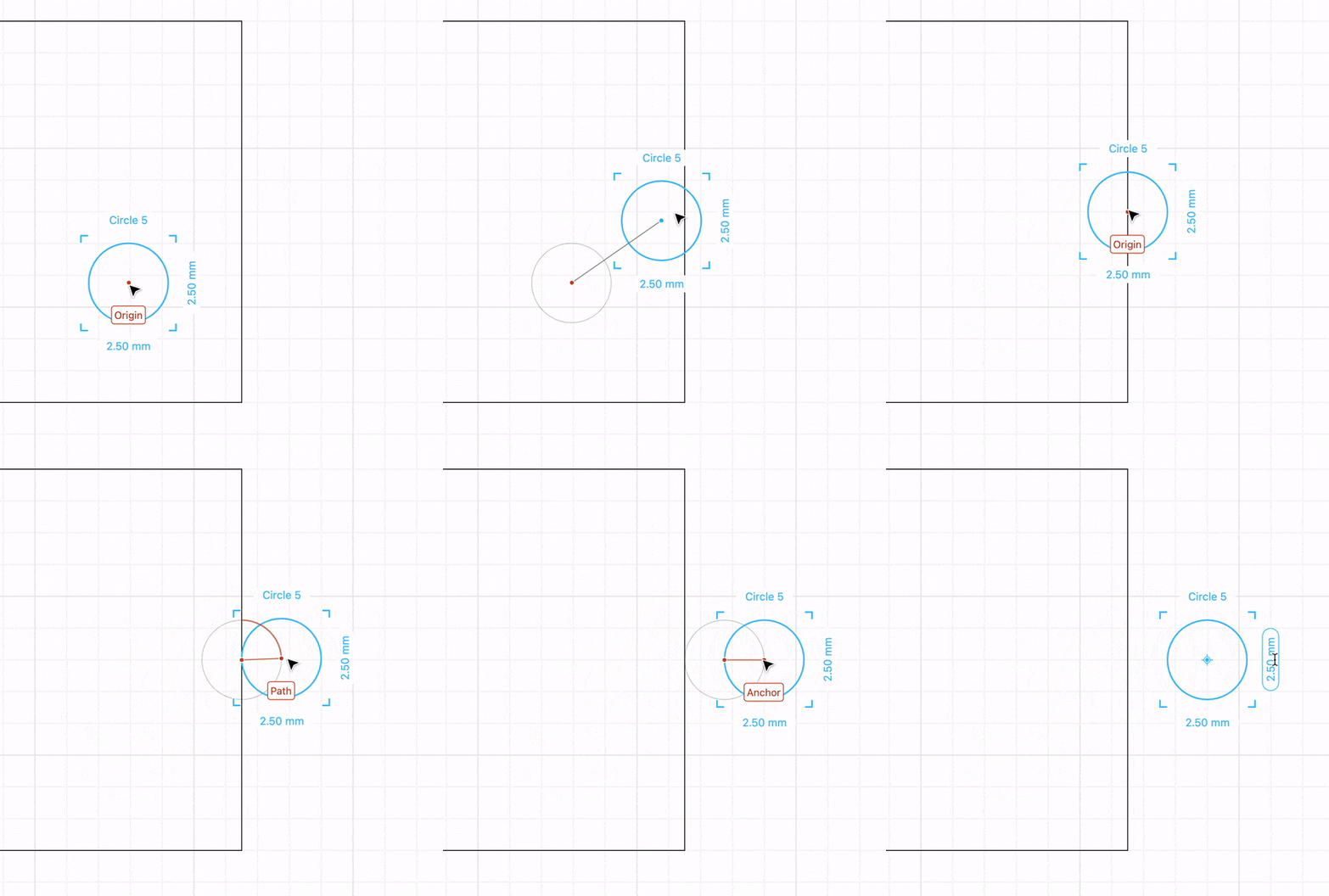
Drag and drop a circle based on the servo’s screw hole diameter.  Adjust the position as shown in the gif below. Copy the hole to the other side.

Select all the lines of your design, right-click and select Group (⌘G / Ctrl+G)

You have now finished the stand design.

  Start by creating a new document and activating the “Grid snapping” option in the toolbar at the top of your canvas. This will help you place components accurately on the grid.

Drag a rectangle a place it in the origin.
Resize to 80 mm wide and 60 mm tall.

Select the rectangle and add a round corner modifier. Add a 3 mm radius rounded corner.

Drag another rectangle size 40 mm wide and 2.8 mm tall (2.8 mm is the thickness of the material we will cut). Place it on the right side edge of the first rectangle you placed and -17.5 mm on the Y axis. This rectangle will create a slot for 2 pieces of wood to intersect with each other and create the stand.

Select both rectangles and perform a “Boolean Difference”. This allows you to subtract one shape from another.

Measure the width and depth of the blue servo motor in your arduino kit.

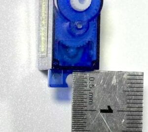
Measure the servo screw hole diameter and its distance from the inside edge.

You have now finished the stand design.

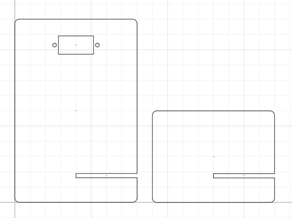
Together your design should look like this. After the second part of the design is completed, you will merge your files together.

Step 1.2: Pattern design

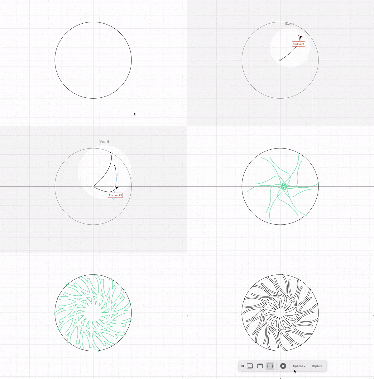
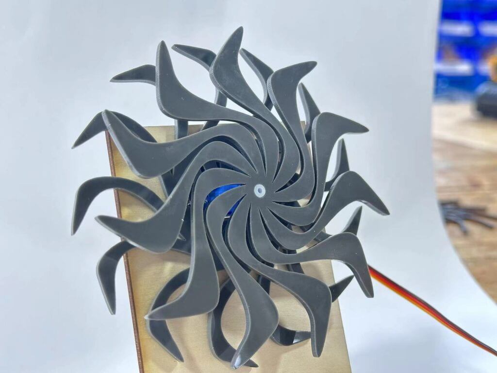
Here is where you get to be creative. Each one of you will design a pattern that when put together will create an interference visual effect. Same as you did during the cuttle.xyz intro tutorial, create a circular pattern of 120 mm in diameter. Feel free to experiment with the tools and shapes until you come up with something interesting. 
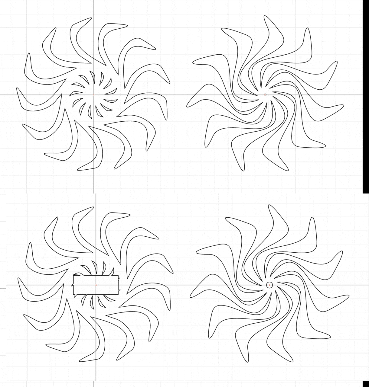
For a more interesting effect, students A and B should design patterns going in opposite directions. 

*Tip: Use the canvas origin point to easily create the circular pattern. If necessary move the previous objects away.

Here is a reminder of the commands used in the tutorial:

      • Create a shape (try using 1 or multiple paths) ->
      • Rotational repeat (the more repetition the better the effect) ->
      • Outline stroke ->
      • Select pattern, right-click, and Group (to make it easier to move around)
      • Tip: You can use the Pen tool to create lines. You can make a curve with the handles of the pen. 


Alright, you are almost done with the design. To finalize you need to find a way to mount the circular patterns.

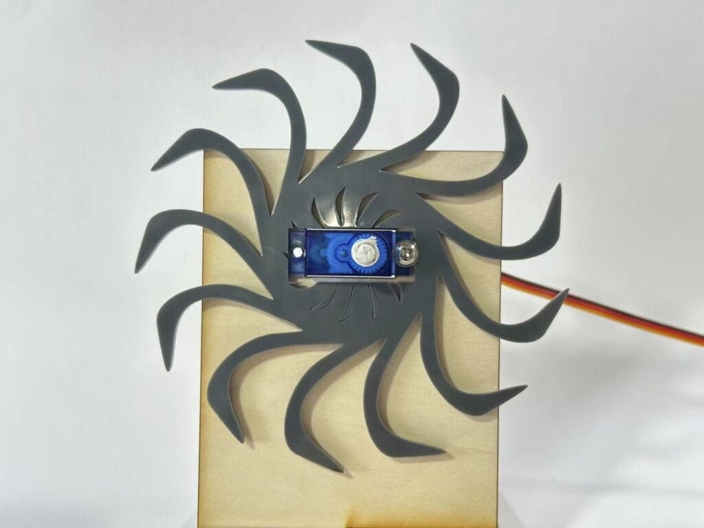
      • One of them will be attached to the stand and will be static with a square cut-out (32.5 x 12.5 mm) for the servo to go through. 
      • The other one will be attached to the shaft of the servo which will move it in a sweep motion. For that create a circle diameter 4.5 mm.


Decide who will make the moving/static part and add the additional features in your design that will allow you to mount your patterns. The implementation should look something like this:

Step 1.3: Export your design

        • File -> Export SVG
        • Create a new folder with your names in this Google Drive and add both of your files.

Step 2: Laser cut

Once you and your partner have finished Step 1, you can now laser cut your parts. For this recitation, you can just go directly to the fabrication lab in 823 but remember that you will need to

Step 3: Assemble 

Assemble your stand with the servo and the circular patterns. You also may need to add a screw to keep everything together. Connect the servo wires to your Arduino with the File > examples > Servo > Sweep example. You should now be able to contemplate the result of both of your designs overlapping each other!

Documentation

Make sure you document the design and fabrication of the entire process. 

Recitation 7: Neopixel Music Visualization

For this week’s recitation, you will be using the NeoPixel Led strip to create light animations for your favorite music!

Materials:

From your kit:

  • 1 * Arduino Uno
  • 1 * USB A to B cable
  • 3 * jumper cables M/M
  • 1 *  NeoPixel strip (WS2812B – Individually Addressable LEDs)

Recitation Exercise:

Task #1: Test the NeoPixel

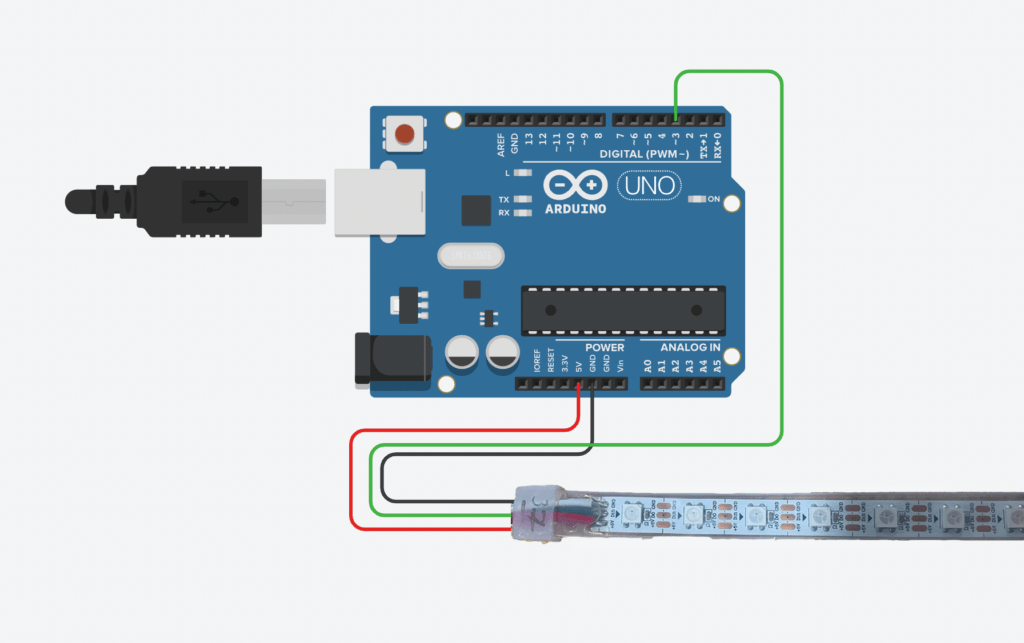
Step 1: Connect the NeoPixel Led strip to your Arduino like shown on the diagram below: 

The NeoPixel strips we use at IMA have is 1 meter long and contains 60 LEDs.  For this amount of LEDs, you can connect directly to the Arduino 5V pin and supply all the current necessary. However in the future, if you work with more than that you might need an additional power source to light up all the LEDs. More info on that here. 

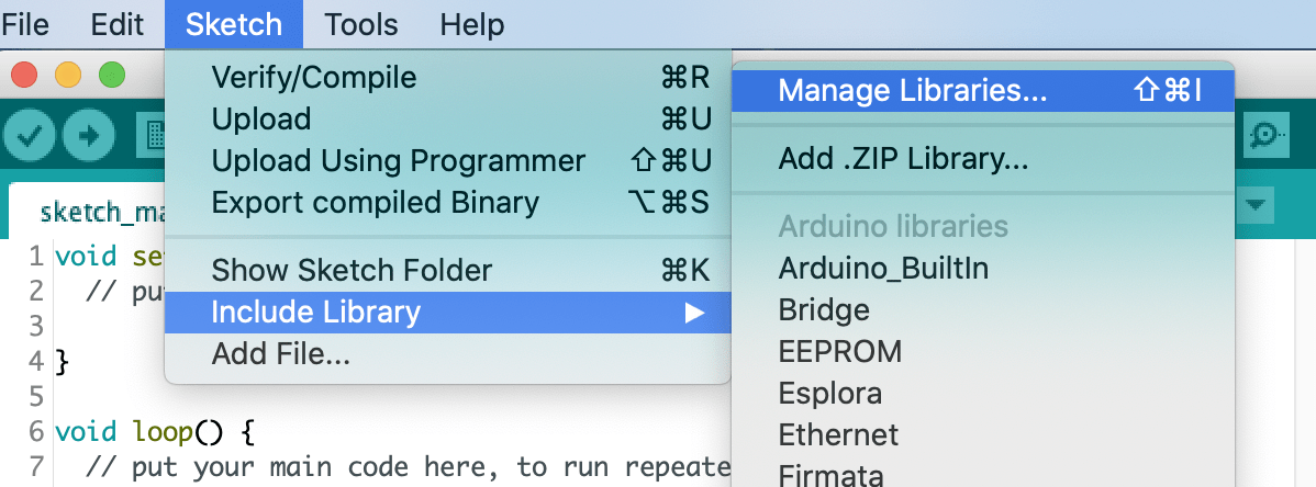
Step 2: Download the library. Just in case you didn’t do this step in class, to control the NeoPixel strip we need to download the FastLED library. To do so go to: Sketch -> Include library -> Manage libraries.
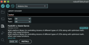
Inside the new library manager window search bar type: fastLED and click Install. 

Step 3: Test the NeoPixels to make sure they are working correctly. You can do that with the example FastLED/Blink. Remember to change the DATA_PIN to the number of the pin you connected the cable to the Arduino board (3 in the diagram we provided you).

Task #2: Use your computer to light up NeoPixels

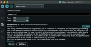
Step 1: Install the SerialRecord library. Similarly to the step you installed for the LEDs. Select from the menu Sketch -> Include library -> Manage libraries, and input SerialRecord. (kudos to Oliver Steele for providing the library)

Step 2: Program your Arduino using the code we used in class, you can copy it from here: IxLab_recitation7_ARDUINO.ino 

Make sure you test your code using the Serial Monitor. This program receives four values, so you will need to send them in a Comma Separated Value protocol (CSV). The first parameter will indicate the pixel number, the second the content of red color, then green, and last blue. For example, to turn the second pixel purple, you need to send 1 the values of 255, a 0 for the second value, and a 100 last, you should input in your Serial Monitor: 1,255,0,100

Remember you might need to press Enter, Return, CMD + Enter, or CTRL+ Enter.

Step 3: Program your Processing sketch using the code we saw in class, you can copy it from here: IxLab_recitation7_PROCESSING.pde

Remember to close ALL the Serial Monitor windows you might have opened. Otherwise, it won’t run and it might show an error of “PORT BUSY”. Similarly, you won’t be able to program Arduino while you have any Processing sketch running. 

Task #3: Add Music!

Step 1: Download this sketch which plays an audio file (located in the data folder) and analyzes the amplitude. Replace beat.aiff with a song you like. 

Step 2: Modify this sketch so that it creates a visualization on the screen AND on the NeoPixel strip. For this, you want to merge code from the Processing sketch from Task into #2 into the current one. Embrace your inner VJ!

Step 3: Add different light effects for the song you have chosen. You can use millis() in Processing to know how long you have been running your sketch. You can use the following sample to do that:

 long t = millis();
 if (t < 1500) {
   background(155);
 } else if ((t>=1500) && t<3000) {
   background(255);
 } else {
   background(55);
 }

Step 4: Have fun with your music visualization! Challenge yourself to add ‘for’ loops, different color visualizations, and finding ways that effects  with the NeoPixels complement what is happening with the screen. Tip: you can use the FFT Analysis to let the colors react to the pitch of the music.

Documentation

Document each task thoroughly, including taking a video. Describe your visualization and record the changes you made to the sample code from Task 3. Upload everything  to the documentation blog.


Recitation 6: Animating an Interactive Poster

Working individually, you will integrate the coding elements from this week’s classes to create an animated poster for the IMA show in Processing.  Requirements:

    • The format of the poster should be the web format: 1024px x 768px.
    • Your poster should contain graphics that change with the time.
    • At least one shape should be of your own design, displayed by a function, and it need to be composed of at least three basic shapes.
    • You should create with Processing all the graphic elements in your poster, this means that you are not allowed to use images or photos. Remember to take a video of your interactive poster demonstrating how it works, and upload it along with your code to the documentation blog. 

Information you might need for your poster:

    • Event: IMA Fall 22 End-Of-Semester Show
    • Location: 8th floor
    • Day: Friday December 16
    • Time: 6pm to 8pm

GRAPHIC DESIGN PINTEREST REFERENCES:

 https://www.pinterest.com/ameliechucky/graphic-design-poster/

ANIMATION REFERENCES:

Here are some animations you can get inspired by. 

anim_1 anim_2 anim_4
asdfd fasdff anim_8
anim_9 anim_10
PROCESSING REFERENCE LINKS USEFUL for your animation:
Loops:

Variables:

Transform functions:

Other Functions:

Homework

Task #1: Add a Fixed Pattern

    • Repeat the design you made in a grid so that it covers the entire screen. You can re-use the function you created in the recitation. The entire window of your sketch should be a repetition of your complex shape. Tip: You can watch this video explaining the way that nested loops work.
    • Make sure you add some variations by adding parameters to your function. Check the patterns below for inspiration:

Task #2: Add a Random Pattern

    • Start a new sketch and copy the function you created in Part 1. Display your design a hundred times in random positions on the screen.
    • Use parameters to give them variation such as random sizes, random colors, random rotation, etc.

Task #3: Make it interactive

You should modify your poster in order to include some level of interaction. You can choose to use the keyboard or the mouse, either by reading the variables or by modifying the graphics when an event happens (e.g. click with the mouse, the user presses the spacebar).

You can, for example, create your own pattern by using the mouse. Draw your design every time you press the mouse in the position where you clicked, and use a press of the spacebar on your keyboard to delete everything on the screen.

INTERACTIVITY REFERENCES:

Here are some animated materials that might serve you as an inspiration for your homework:

anim_3anim_

PROCESSING REFERENCE LINKS USEFUL for your Interaction:
Keyboard interaction:

Mouse interaction:

Environmental variables:

Documentation


Upload the screen recording (video) of your interactive animation along with your code (copy-as-HTML) to the documentation blog. Include both the recitation and homework in your post.

To record your screen on Mac press   Shift + Command + 5   
To record your screen on Windows press  Windows key + G 

/**
 To share your code appropriately in your blog post:
  - Select all your code -> Copy as HTML
  - In your blog post go to "Text" editor, top-right of the window.
  - Copy and switch back to "Visual"
 */

Another option is to put your code on Github Gist and paste the link in your post. If you don’t have one yet, a free Github account is totally worth getting! It’s a sometimes complicated but very useful developer tool, with a great open source community!

Write some comments about what you learned during this exercise, for example, list the most interesting functions you used or what you struggled with. Be thorough so that you can refer to these notes in the future. 

You can work on the assignment on your own, or join one of the Study Sessions hosted by our amazing LAs to learn how to make this! 

rainbow study session

Rainbow Group Study Sessions

Dates:

Monday Nov 7  | 5:30-6:30 pm

Wednesday Nov 9th  | 5-6 pm

Location:

826 Studio

Recitation 5: Processing Basics

For today’s exercise, you will be working individually to draw an image in Processing based on a photograph that inspires you.

Step 1: Choose your motif

To complete this exercise, you will need to select a photograph image as a motif. You can take this image now, but more likely you’ll be selecting an existing photograph from your album. The motif of your image is up to you – but try to select an image that has an aesthetic quality (e.g. in light/shadow, composition, colors), and also a number of geometric features, since Processing is well-equipped to render those.

Step 2: Draw your image on paper

Use the photograph as a starting point, or inspiration, to draw a new image on paper. This won’t be purely reproduction of the photograph: you might want to omit certain features, simplify/abstract elements so that you can form them out of the drawing functions in Processing we covered, rearrange others, etc.

You should use graph paper for your sketch so that you can easily determine the positions of the elements if needed. Do this before you begin coding. You must include a photo of your hand-drawn graph paper in your documentation.

Step 3: Draw your image with code

Start a new sketch in Processing and build the image using code, following your paper sketch. Your canvas size should be at least 600 x 600 pixels. Start out with the following structure:

void setup() {
  size(600, 600);
}

void draw() {
  // Your drawing code goes here
  background(255);
}

As you work on it, using the functions and methods covered in class, you can modify shapes and adjust colors to enhance your design further.

Here a list of some of the available drawing functions in Processing for you to use:

For other functions and questions, please review the Processing tutorials page and the Processing reference.

[Optional] Step 4: Going beyond

If you finish your drawing early and want to challenge yourself, consider tackling one or more of the following options:

            • (a) Select an element in your composition and animate its position using code. (You would change a coordinate for a global variable, whose value you modify inside the draw function – so that every time through draw, the position will be slightly different.)

            • (a+) Use a conditional to make the element re-appear once it has gone out of the frame.
            • (b) Select an element of your composition and give it some controlled degree of randomness – e.g. in its position, size, or exact color. (You would introduce global variables to hold these values, and use the random() function inside setup to pick randomized numbers – thus producing a slightly different image every time the program runs.)
            • (c) Modify the colors in your drawing to use a carefully chosen color palette, which amplifies the atmosphere of the situation your image depicts, rather than using natural colors. (consider e.g. Bauhaus School of Arts, or Edward Hopper for inspiration).

Documentation

Document your work on your blog. Start by uploading the image you chose, and add a description of why you chose this image. Then, discuss what and how you wanted to draw it in Processing, and your method of achieving that goal. Consider how your final creation is linked to photograph and paper drawing – and in what ways it is similar and different. Don’t forget to upload the sketch you made on paper. Do you think that drawing in Processing was a good means of realizing your design? Please make sure to post your code and a screenshot of your final sketch in addition to the information above.

You should copy your code as HTML and insert it in your blog post instead of taking a screenshot. Ask for help if you don’t know how to do this.

Additional references:

Recitation 4: Actuators and Mechanisms

/* (!) Disclaimers:

1. This recitation requires you to work with higher voltages. If the circuit is not built properly in accordance with the provided schematics, there is potential to damage your computer if you are not using USB protection. If you choose to use your computer for this recitation, please notice that you are doing so at your own risk. If you do not feel comfortable using your own computer, you can check out an IMA laptop from the Equipment Room.

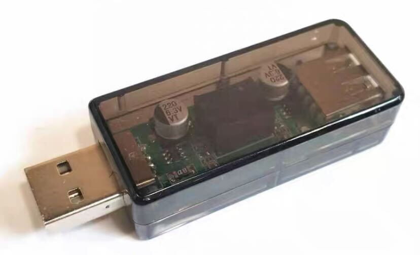
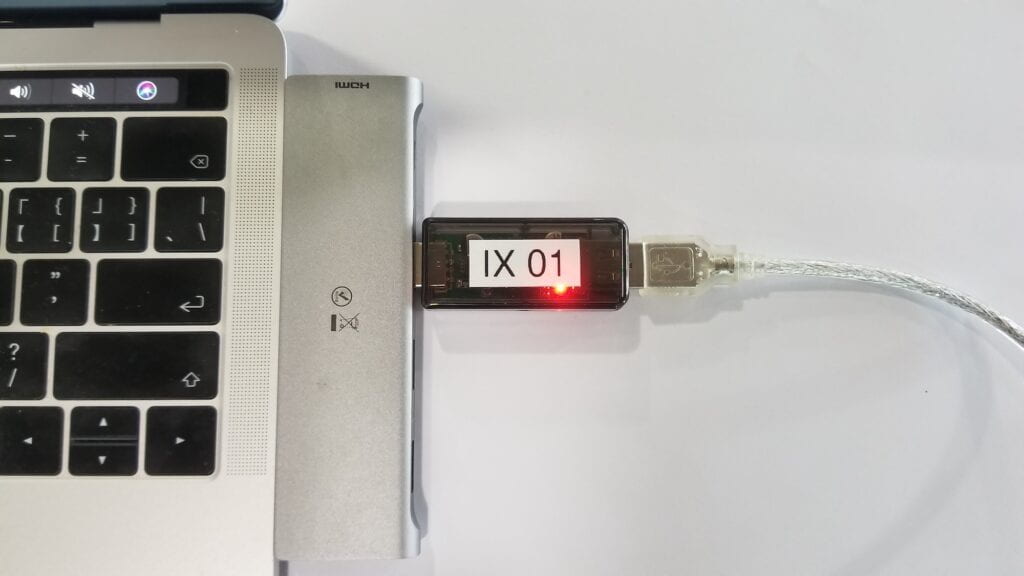
2. To prevent your computer from accidental damage, therefore use the provided USB protector, which plugs in between your computer and the Arduino.

3. The components in this recitation (the IC and Stepper Motor) will get hot, so please be mindful and do not touch these components when they are powered. */


This week, we will be creating a mechanism out of cardboard. You will work together with a partner. You only need to build one mechanism and one circuit, so you should make sure that you help each other to complete all the steps. 

Step 1: Build the circuit

Materials needed for your circuit:

Qty Equipment Photo
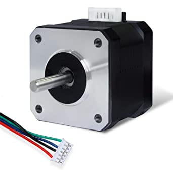
1 42STH33-0404AC stepper motor
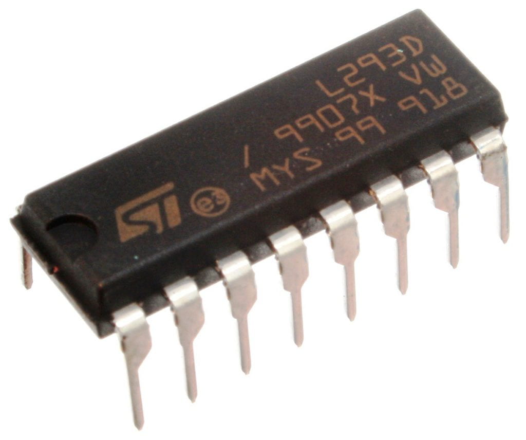
1 L293D chip (H-bridge) L293D integrated circuit
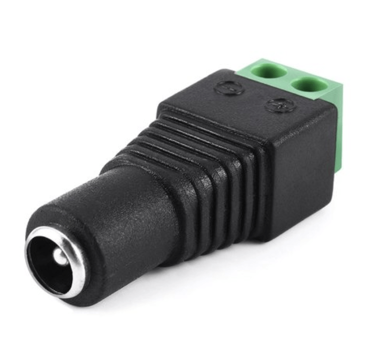
1 Power jack
1 12 VDC power supply
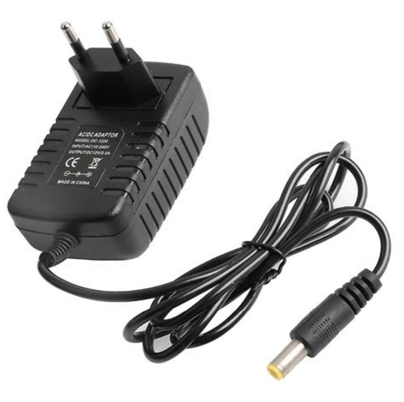
1 USB protector
1 Arduino UNO, USB cables, jumper cables, and breadboard (included in your Arduino kit)


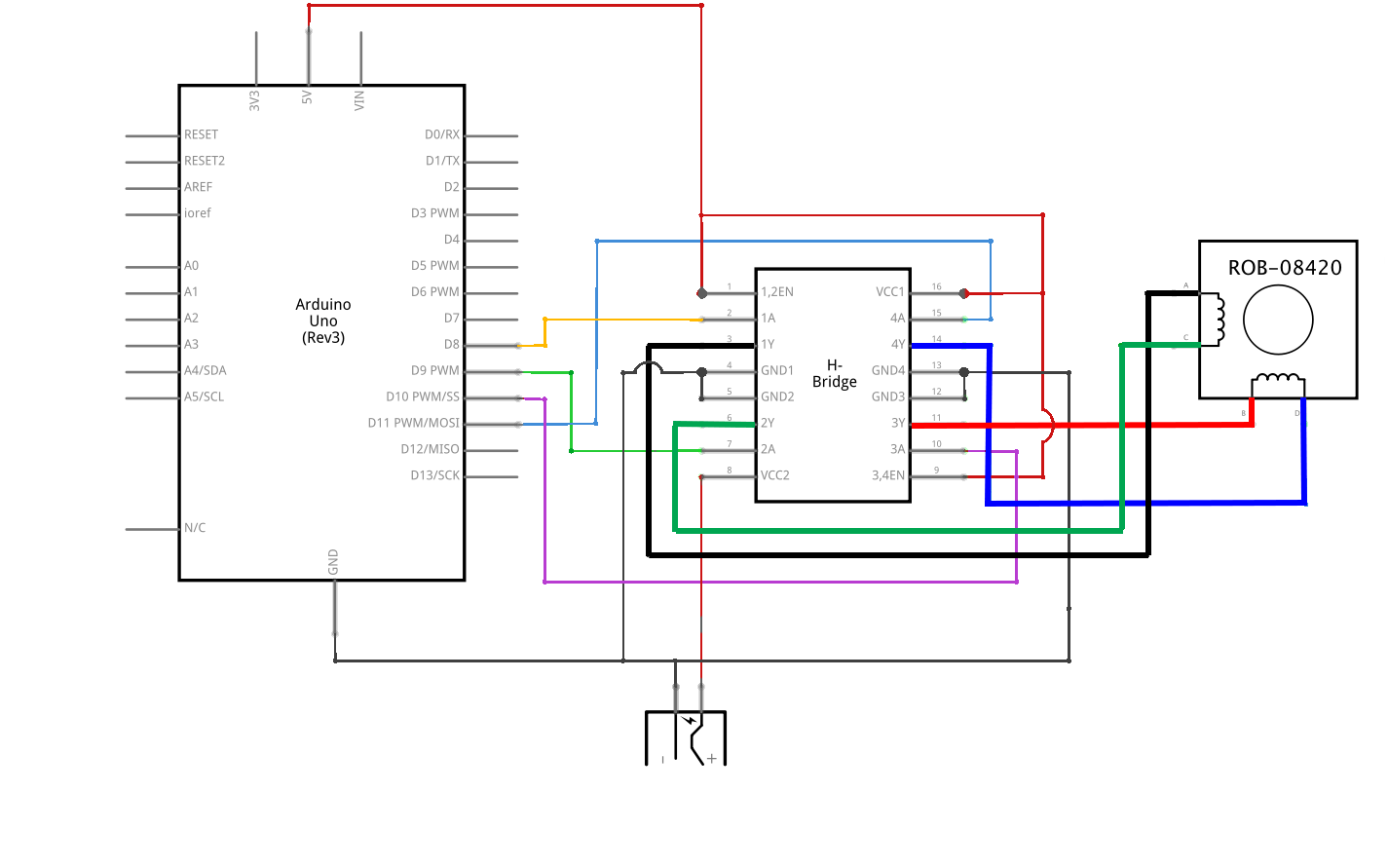
You will be making the bipolar circuit for the example code Stepper > stepper_oneRevolution (the same code is also available online for you to copy). First, build the following circuit to control the stepper (click to enlarge).

/* Important note:
To protect your computer from possible damage, use the USB Protector to connect the Arduino to your computer:  */


H-bridge circuit diagram

/* h bridge
Make sure you orient the IC in the correct position; The IC has a front and a back. A semicircle indicates where the front of the IC is. The pin to the left is pin 1, and the diagram beside depicts how the other pins are numbered.
*/

If your wiring is correct, and you have programmed your Arduino with the Stepper > stepper_oneRevolution example (also available online) sketch, your motor should rotate smoothly and make one revolution. Only if your motor rotates evenly, you should continue with Step 2.

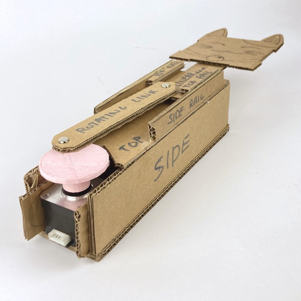
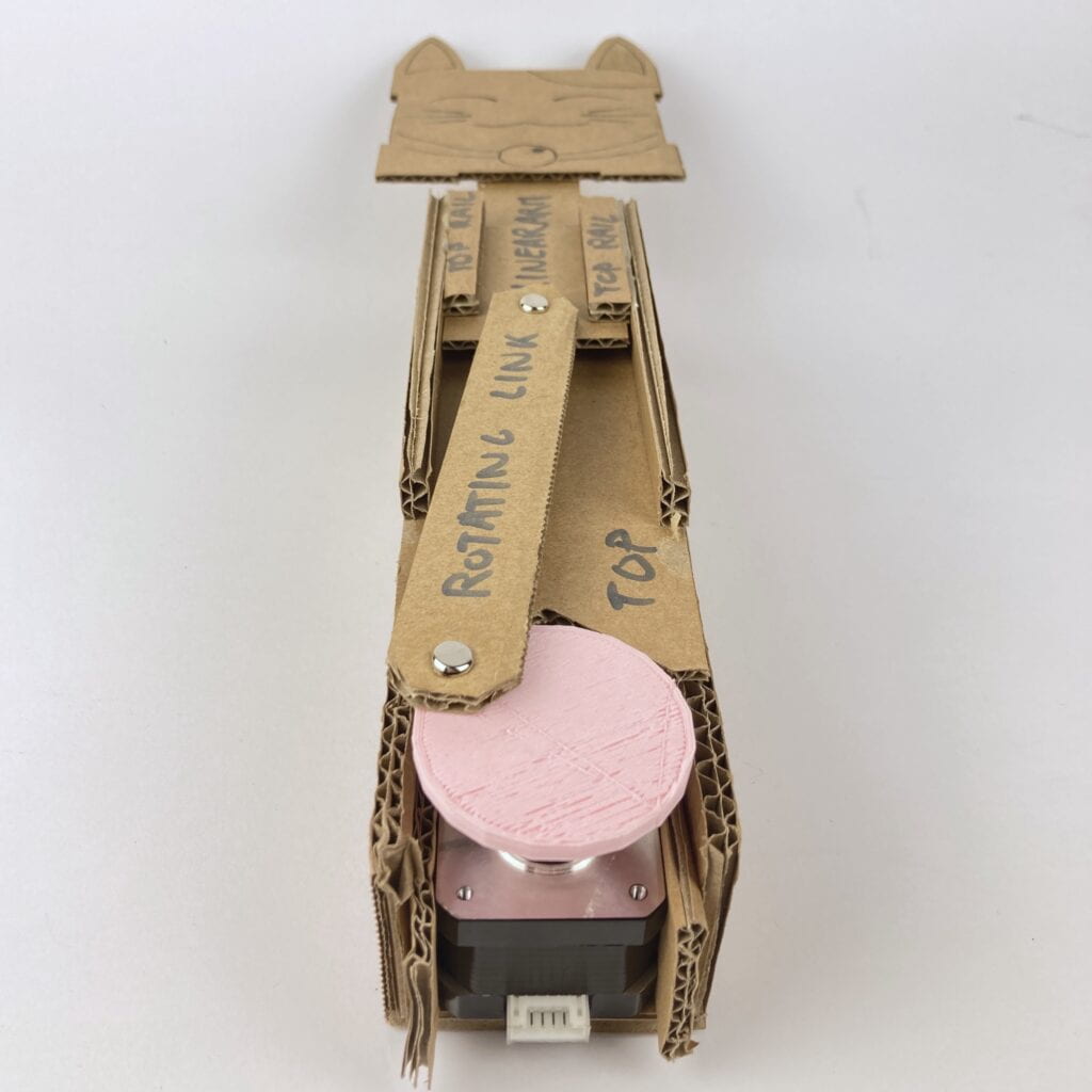
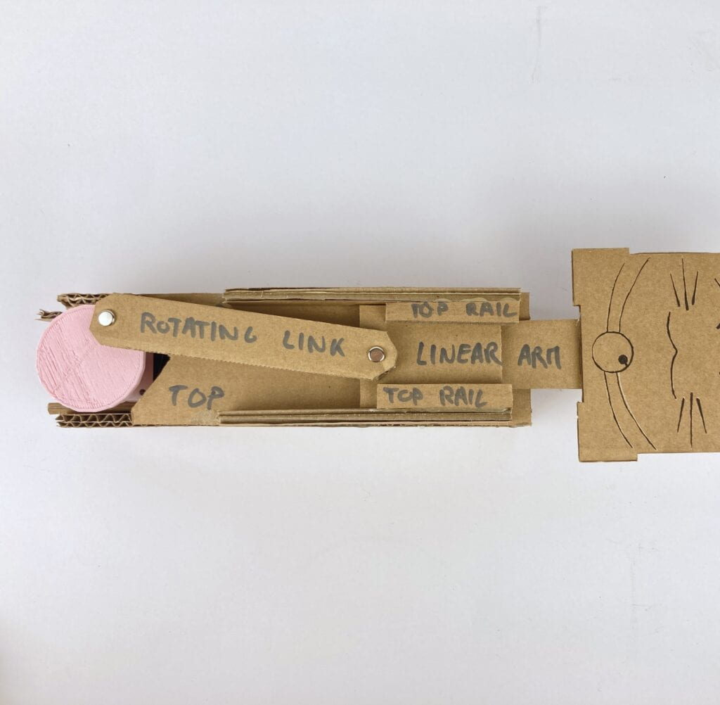
Step 2: Build a cardboard mechanism!

Materials needed for your cardboard mechanism:

Qty Equipment Photo
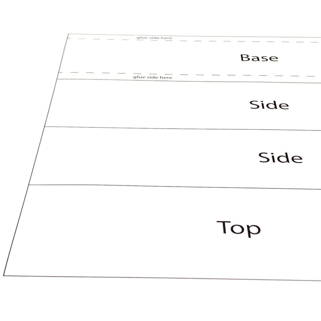
1 Template Cutting template
1 Cardboard sheet  
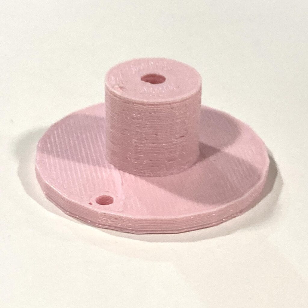
1 Shaft adaptor Shaft adapter
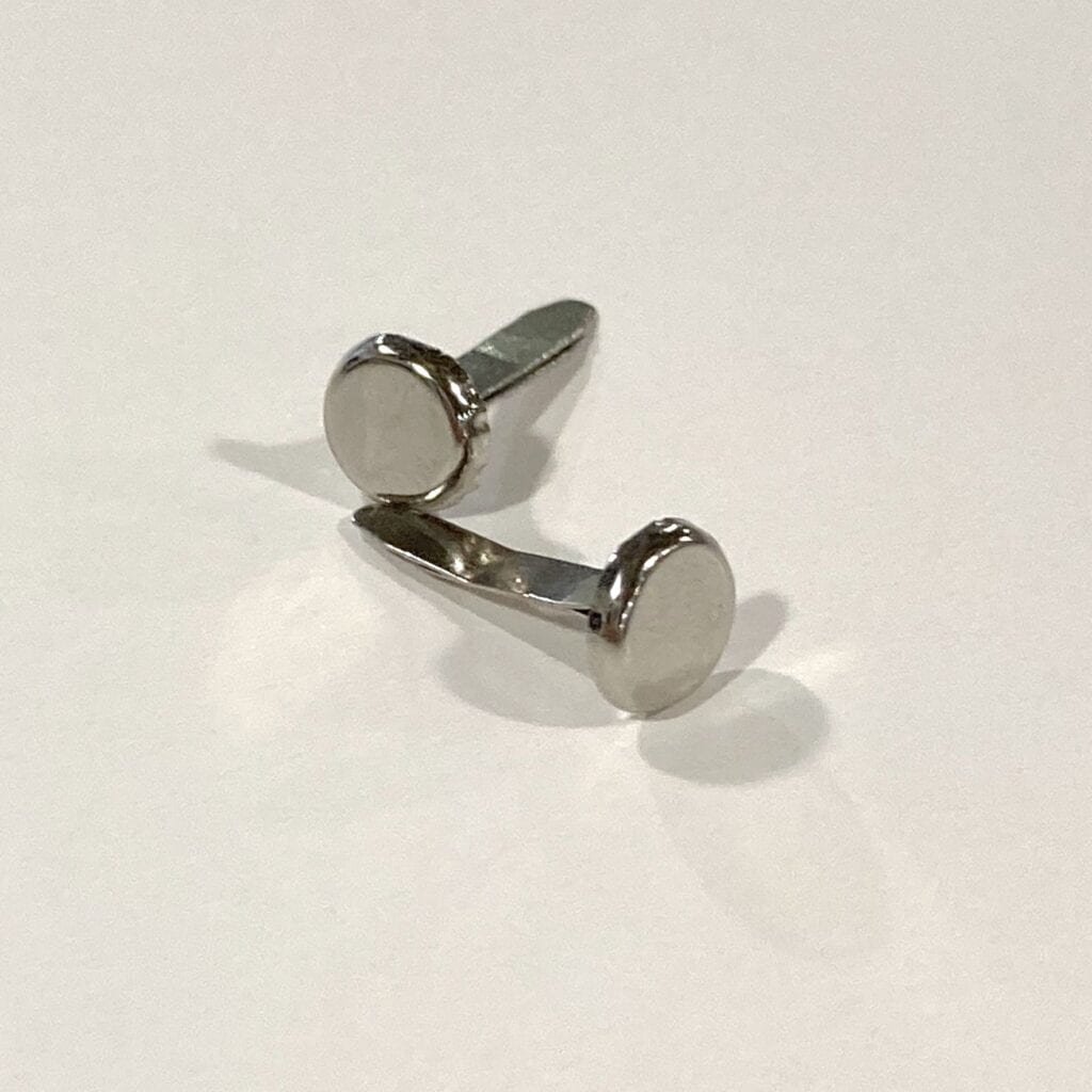
2 Rivets Rivets
1 Hot glue gun + glue sticks (included in your toolkit)
1 Box cutter (or utility knife)


Once you and your partner have finished Step 1, pick up one template and a sheet cardboard for your mechanism building activity. Since the stepper motor will be embedded in your cardboard mechanism, unplug it from your breadboard while you build (and reconnect it later to test).

Start by attaching the template onto the textured (“bad”) side of the cardboard using the glue stick. Now you can can cut out the different parts using the ruler and the box cutter in your toolkit. A few parts require you to punch a small hole through the cardboard through which rivets will go, connecting two pieces of cardboard. The pointy tip of your soldering iron makes a good hole.

/* Important note:

1. If you are unfamiliar with a tool, ask how to use it to any instructor, fellow researcher, or learning assistant.

2. You will need to use a cutting mat under the surface you cut. Do not damage the tables of our studio!

3. Place a paper or cardboard under your hot glue gun. Pay special attention because it might damage belongings (and fingers!). */

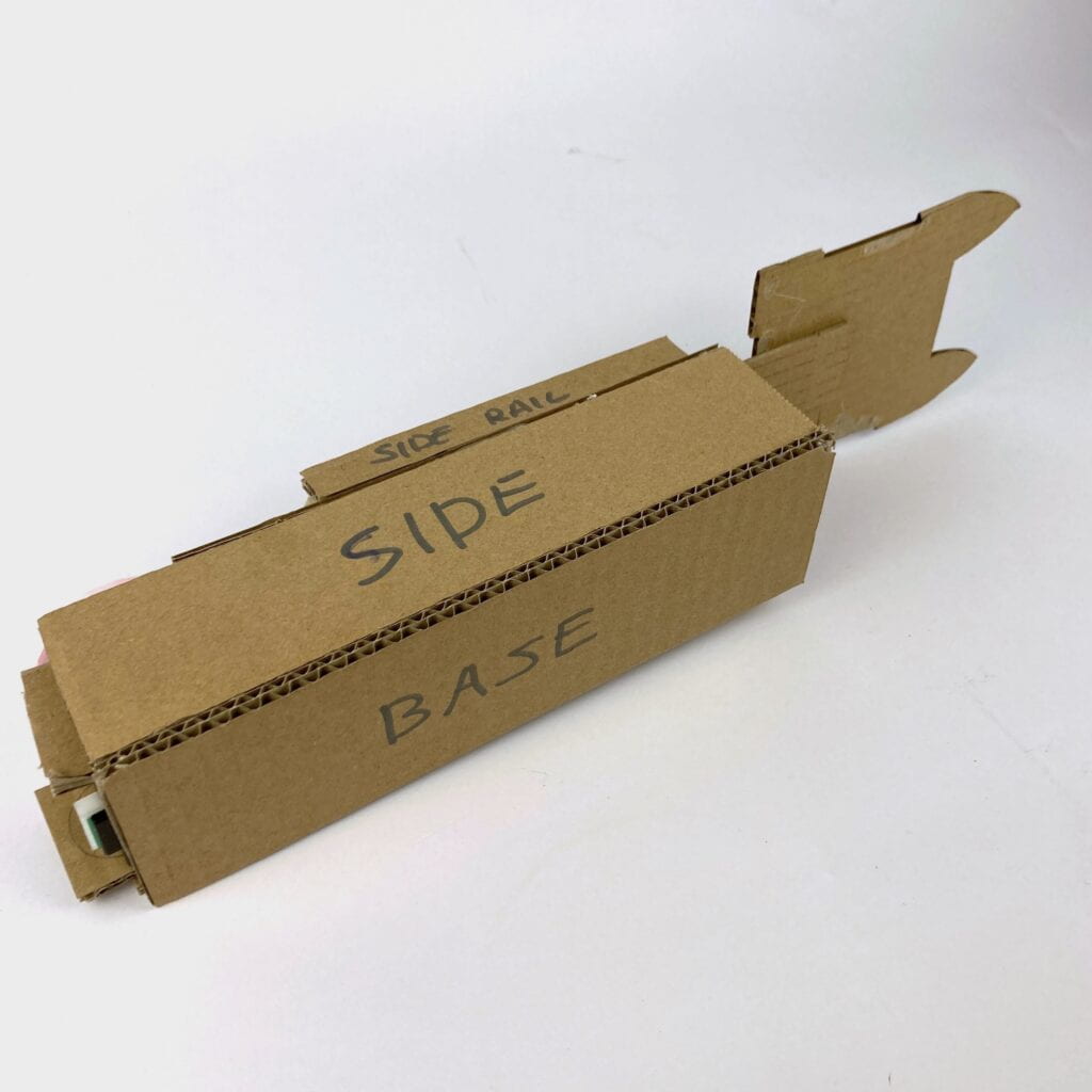
Next, glue together the different cardboard pieces using the hot glue gun. (Feel free to remove the paper template at this point, if you like, once you know where the part will go.)

Assembly 1 Assembly 2
Assembly 3 Assembly 4


Punching hand


Step 3: Personalize it

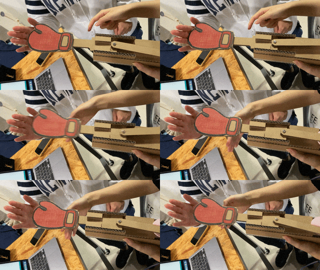
Together with your partner, modify your mechanism to tell a tiny story. What could it represent? A boxing glove that punches? A piston in an engine that moves? Consider adding appendages to your mechanisms – add paper or cardboard – use it sideways – etc.

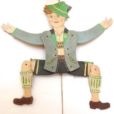
Hampelmann

Modify the code so that the movement is coherent with your chosen narrative. E.g. the arm of a boxer will move forward much more quickly, before stopping, and pulling back. Use delay(), myStepper.setSpeed(), myStepper.step() , and random() to this end.

Don’t forget to continue using the USB protector as you’re working on this! Document the motion you came up with in a video.

Documentation

Make sure you document the process and the result of your circuit and mechanism building. Additionally, answer the following questions your answers:

Additional Questions

Question 1: Choose an art installation mentioned in the reading ART + Science NOW, Stephen Wilson (Kinetics chapter). Post your thoughts about it and make a comparison with the work you did during this recitation. How do you think that the artist selected those specific actuators for his project?

Question 2: What kind of mechanism would you be interested in building for your midterm project? Explain your idea using a sketch (conceptual or technical) with a list of materials that you plan to use. Include details about the ways that you expect the user to embrace in a physical interaction with your project. In particular, explain how would your motor (or motors) with a mechanism will be different than using an animation on a digital screen.

Recitation 3: Workout

For this week’s recitation, you will be also doing some workout! You will use the tilt switch from your kit to build a wearable workout sensor, do a workout exercise, and complete a challenge. You will work in pairs, but each person will need to make your own circuit.

Remeber to document the process for your blog documentation, and futher descriptions about the documentation can be found at the end of the post.

Materials:

From your kit:

        • 1 * Arduino Uno
        • 1 * USB A to B cable
        • 1 * breadboard
        • 1 * tilt switch
        • 1 * 10k ohm resistor
        • A handful of M/F, M/M, and F/F cables

From course supplies:

        • 2 long wires (about 1.8 m)
        • 1 capacitor 0.1 uF (confirm size)

Recitation Exercise:

Step 1: Prepare your tilt sensor

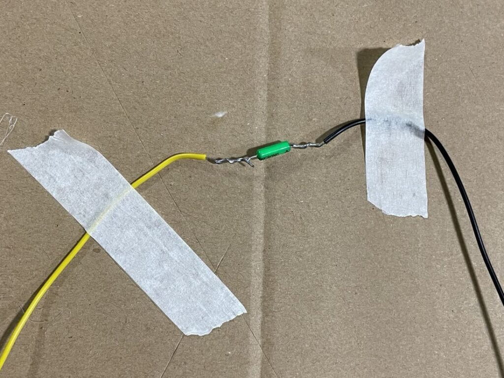
Task #1: Solder the sensor to two long wires. Pay attention to your safety and take care of your workplace. You can optionally cover the soldered parts with electrical tape or a heat-shrink tube for safety and stability.

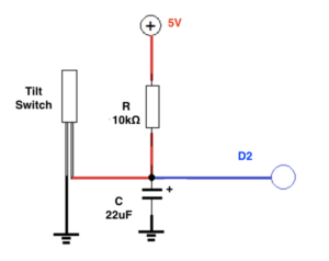
Task #2: Connect the tilt sensor cables to your Arduino using a capacitor as the circuit below:

tilt-22uF-10k

Task #3: Program your Arduino with the following sketch. Confirm that you get an input from your tilt sensor on the the Serial Monitor to check whether it is working correctly.

int SENSOR_PIN = 2;    
int tiltVal;

void setup() {
  pinMode(SENSOR_PIN, INPUT);    // Set sensor pin as an INP
  Serial.begin(9600);
}

void loop() {
  // read the state of the sensor
  tiltVal = digitalRead(SENSOR_PIN);
  Serial.println(tiltVal);
  delay(10);
}

Step 2: Refine the code

Task #1: Upload the following sketch to only print 1 when the tilt sensor changes from 0 to 1, and 0 when from 1 to 0. For example, the code we used before might  have printed 0 0 0 0 1 1 1 1 0 0 0 0 1 1 1 as you move the sensor between upright and upside-down, but now your code should print 0 1 0 1.

int SENSOR_PIN = 2;
int tiltVal;
int prevTiltVal;

void setup() {
  pinMode(SENSOR_PIN, INPUT); // Set sensor pin as an INPUT pin
  Serial.begin(9600);
}

void loop() {
  // read the state of the sensor
  tiltVal = digitalRead(SENSOR_PIN);
  // if the tilt sensor value changed, print the new value
  if (tiltVal != prevTiltVal) {
    Serial.println(tiltVal);
    prevTiltVal = tiltVal; 
  }
  delay(10);
}

Step 3: Wear your sensor

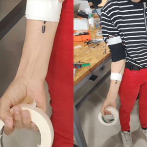
Fix the tilt switch using paper tape to your body, making it a wearable sensor. The sensor should be along your forearm, so that you can use it to detect when your forearm is facing up.

Step 4: Bicep Curl Workout!

Image from Icedgif.com


Task #1: Add a conditional to your sketch so that it shows  a message on the Serial Monitor ONLY when a full biceps curl has been completed. Remember to switch from the Serial Plotter to the Serial Monitor. You can comment existing lines of code with //.

You will need to :

          1. Identify the proper section in your code where you can add code when transitions happen.
          2. Add a conditional that has the criteria so that you only detect transitions LOW to HIGH, showing only when the user has raised their arm completely. 

Task #2: Count the curls, adding one to its value every time that the user does a complete bicep curl. You should:

          1. Declare a global variable.
          2. Add one to its total every time that a LOW to HIGH transition has happened.
          3. Modify the Serial.print and Serial.println instructions so that the value of this new variable is shown on the Serial Monitor.
    1.  

Task #3: Set a limit to the variable you are using to count the curls, so that the final code has the following behavior.:

          1. When the total reaches 8, Print “Yay, you’ve done one set of curls”. Hint: you will need another conditional
          2. Reset the count, so that the behavior repeats at 16 curls, 24, etc.

Step 5: Exercise Challenge

You should design a different physical exercise (not bicep curls). The user will have to wear the sensor according to the physical movement, you should test it with a partner, and receive feedback.

Some ideas that could complement this challenge:  

        • Add a buzzer and modify the code so that it “celebrates” each completion of each set of exercise.
        • Add a vibration motor to your circuit and modify the code so that it  gives haptic feedback for each exercise.
        • Add a potentiometer to your circuit, so that the user can configure the number of repetitions in a set.
        • Add a second tilt sensor to your circuit. Count two people’s exercises on the same Arduino.
        • Give the user instructions to follow using the Serial.print. For example, when the sketch starts, it prints “Start your Workout”.
        •  Make it a time sensitive activity. For example, after 20 seconds, it stops counting and it prints “STOP! Your time is up!”.
        • Detect when the user has stopped doing the exercise before the set is done. Prompt them on the Serial Monitor. 

Documentation:

      1. Record a short video of yourself doing step 4 (bicep curls) and 5 (challenge) while showing the Serial monitor/plotter in action.  

2. Embed your code into your blog as shown with the example codes in this recitation, NOT by taking a screenshot of it.

3. Draw your own illustration sketches that showcase how a person would use this interactive training device.

4. Reflect on your experiments, explaining the notes you took, and adding photos, and/or screen shots to document what tests you have tried and what you have learned from them. As a guidance, use the following questions:

          • At what angle of tilt does it transition between HIGH and LOW?
          • What else did you notice about its behavior?
          • What if you rotate the limb that has the sensor attached to it?
          • What if you shake it?
          • What if you hold the wires several centimeters away and tilt it?
          • Do you think it can be used by any user?

Recitation 2: Arduino Basics

Recitation

Instructions:

In this recitation, you will build three circuits: Circuit 1: Fade, Circuit 2: toneMelody, and Circuit 3: Speed Game and run them using the example code. Document your process making them, as well as each of the assembled circuits.

Materials:

  • 1 * Arduino Uno
  • 1 * USB A to B cable
  • 1 * Breadboard
  • 1 * Buzzer
  • 2 * LEDs
  • 2 * 220 Ohm resistors
  • 2 * 10 kOhm resistors
  • 2 * Pushbuttons
  • A handful of jumper cables

From the Cart (optional, only if you need them):

  • 1 or more * DIY paddles (cardboard buttons from Recitation 1)
  • 1 * Multimeter
  • 1 * USB-C adapter (You should purchase your own after this recitation if you need one. Some don’t work well with Arduino, but ours do. We bought them here.) 

Circuit 1: Fade

Work individually to build the “circuit 1: Fade” following the circuit-building part of the instructions here: https://docs.arduino.cc/built-in-examples/basics/Fade. When you finish building, access the code from Arduino IDE > File > Examples > 03.Analog > Fading and upload it to your Arduino. 

Circuit 2: toneMelody

Work individually to build the “circuit 2: toneMelody” following the circuit-building part of the instructions here: https://docs.arduino.cc/built-in-examples/digital/toneMelody. When you finish building it, access the code from Arduino IDE > File > Examples > 02.Digital > toneMelody and upload it to your Arduino.

Circuit 3: Speed Game

This is a two-player game where each participant races to click a button more quickly than their opponent. Whoever has clicked their button ten times the fastest wins!

This circuit is provided as a layout diagram instead of a schematic, so as part of your submission for this recitation, draw your own schematic of how the components are connected.

To build the game, work in pairs:

1. Sign in with your Tinkercad account, or sign up if you don’t have one yet. (Please remember your login since you will also use it for the rest of the semester.)

2. Open the Speed Game Example. Click “Copy and Tinker” to view the layout diagram and code.
3. Connect the circuit accordingly and copy the code into your Arduino IDE. Run the program.

/* Tips: 
   1. In Tinkercad, you can click on an electronic 
   component to view its name and parameters (for example, 
   resistor, value: 220). 
   2. Click the "Code" button to view the code.

*/

4. To play the game, first open up the Serial Monitor in the Arduino IDE for instructions. To start the game over, press the Reset button (the little red one!) on your Arduino Board.

Document you and your partner interacting with the circuit. If you have extra time, here are two optional steps:

1. Switch out the pushbuttons with the DIY paddles you soldered during the previous recitation.

2. Find another group and combine your circuits to make a four-player speed game.

Documentation

Please post your responses to the 3 questions below, along with the other documentation for the circuits that you built. Don’t forget to include an explanation of your process of building the circuits, how you solved any difficulties you encountered, and your own drawing of the schematic for circuit 3!

Question 1: Propose another kind of creative button you could use in Circuit 3 to make the game more interactive. Read and use some material from the Physical Computing, Introduction Chapter (p. xvii – p. xxix) to explain why this button would make this game more interactive.

Question 2: Why did we use a 10 kOhm resistor with each push button? (Psssst… Go back to your slides for this answer)

Question 3: In the book Getting Started with Arduino there is a clear description about the “Arduino Way” in chapter 2. Find a project that you find interesting that can be used as an example for these kind of projects. Cite it in adequate manner, include a picture, and explain the reasons that you chose it.

Recitation 10: Image & Video

In this recitation, you will work individually to explore using physical controllers to modify the way in which media is being (dis)played. Reflect on this week’s classes to guide you in your coding process and think about how you can incorporate interactivity and computation into this week’s exercises.

Today’s task: Media controller Create a Processing sketch that controls media (image or video) by manipulating that media’s attributes using a physical controller made with Arduino. For the serial communication, use the examples of the SerialRecord library as a starting point (e.g. SendMultipleValues on the Arduino, and ReceiveMultipleValues on the Processing side).

Arduino:

For the physical controller, incorporate digital and/or analog input via your Arduino. These inputs should manipulate the media in your Processing sketch by serially connecting Arduino to Processing and sending your Arduino’s inputs as values to Processing. The relationship between the Arduino input controls and the Processing media manipulation should have a clear correlation (i.e. the ultrasonic ranger to adjust an analog value, like video speed or image size).

Processing:

You may choose to use the video or live video via webcam or images as the media you will control in Processing.

Consult the slides from class 22 and class 23 to learn about the different methods available for manipulating how images and videos are being played back or displayed. More information, including examples, can be viewed on the Processing website: Image, Video.

If you do not have authorship over the media that you use for this exercise, make sure you credit the source. Here are a few resources for public domain and creative commons sounds, videos, and images. You can use those for this recitation, don’t forget to credit the source:

Documentation

Document your work on your blog, detail how your process of building the circuits and writing the code went. In addition, upload a video of your exercises in action. Any success? Any failures? What did you learn?

Recitation 1: Electronics & Soldering


/* * * * * * * * * * * * * * * * * * * * * * * * 
Welcome to the 1st Interaction Lab recitation!
Here are a few things to help you get started:
1. At the beginning of each recitation, please carefully read through all the instructions,
 material list,  and references (if any). 

2. While you are reading, you will be called upon to take attendance(with your campus card)
 and collect materials for the tasks.


3. It is very important to document your work properly.
 For each task, you should take pictures and/or videos of the finished circuit working, 
as well as the important steps of the building process, such as problems you encountered, 
and how you fixed them. Take notes on questions you had and lessons you learned.

4. If you have any questions, eagerly seek help and ask questions from  professors, fellows,
or learning assistants. Documenting the questions you have and the help you get with them 
is useful in your written documentation.

5. Return all materials you have borrowed at the end of recitation. If you finish the tasks 
early, don’t leave unless you buy bubble tea for everyone. 

6. If you aren't able to finish the tasks, you can come to the 826 studio during the opening 
hours to continue working. The fellows, learning assistants or any professor can help you to 
check out materials you need. 

Have fun!
* * * * * * * * * * * * * * * * * * * * * * * */

Recitation #1 Materials:

Collect these materials from the bins provided. For clarification on what components look like, please consult the Reference section at the end of the instructions.

  • 1 * Breadboard
  • 1 * Buzzer
  • 1 * Push-Button Switch
  • 2 * 220 ohm Resistor
  • 1 * 10k ohm Variable Resistor (Potentiometer)
  • 2 * LED
  • 1 * 5 volt power supply
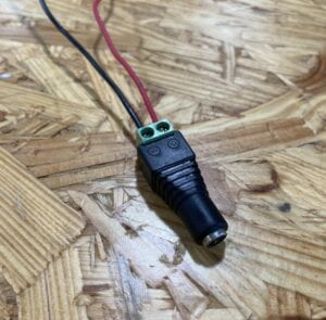
  • 1 * Barrel Jack (Power)
  • 1 * Multimeter
  • 1 * DIY Paddle Button
  • Several Jumper Cables (M/M Wires)

You will make this during the recitation:

  • 1 * DIY Paddle Button

Recitation #1 Tasks:

For these tasks, find a partner and work in pairs to complete the following tasks:

Task 1: Build the circuits

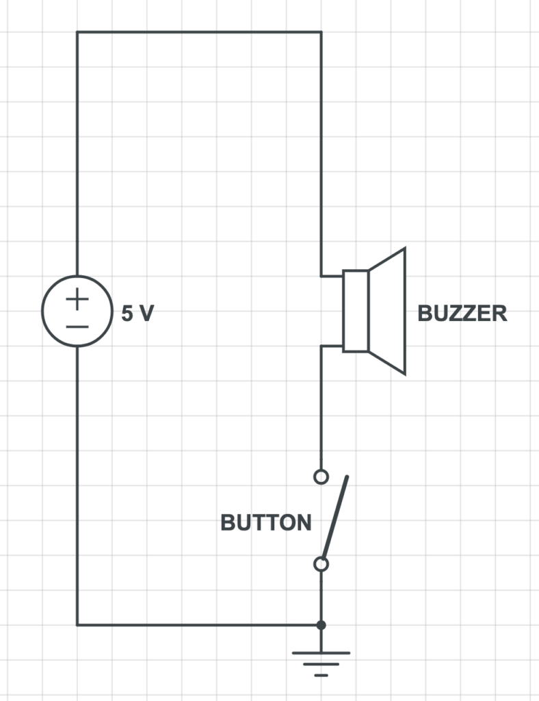
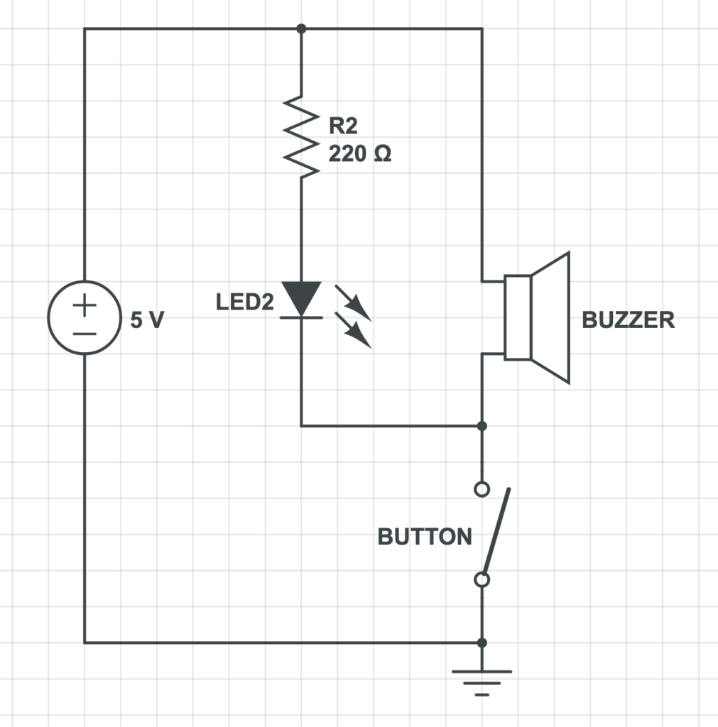
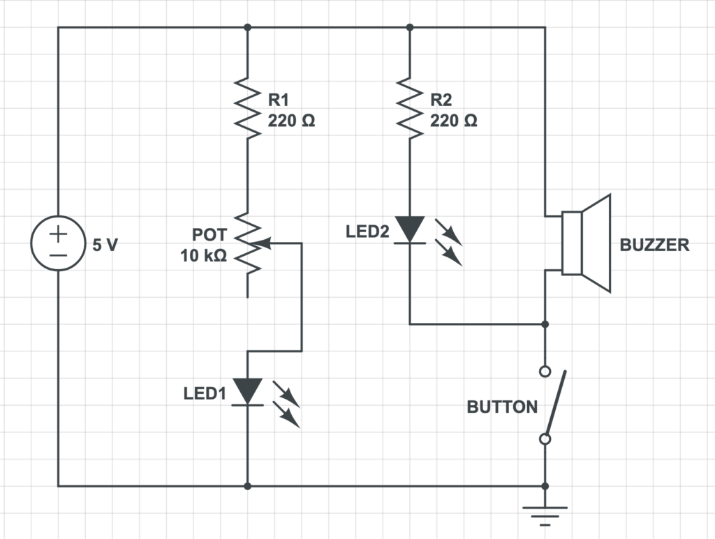
With your partner, build each circuit on a breadboard based on the provided schematic. To simplify the process, you will build the circuit incrementally step by step. When you’ve finished, take pictures and a video of the finished working circuit. Record notes about the building process, such as problems that you encountered, and how you fixed them.

Note: To help you read the schematics for the circuits, look at the components and their symbols at the end of this document in the section “Reference: Components and Diagrams”, or refer to the diagrams in this reading.

Step 1:

STEP1

Step 2:

Remember to document the circuit you have built in Step 1, and continue building with the following diagram:
STEP2

Step 3:
STEP3


Task 2: Build a switch

Individually, use cardboard, copper tape, and wires to build a switch. You will be brought to soldering stations to complete this task. There, each of you will make one DIY paddle with long wires and copper tape that you will combine into a cardboard switch.

Task 3: Switch the switches and send a message

Once you have completed the DIY paddle switch, replace the push button with the newly soldered DIY paddle.

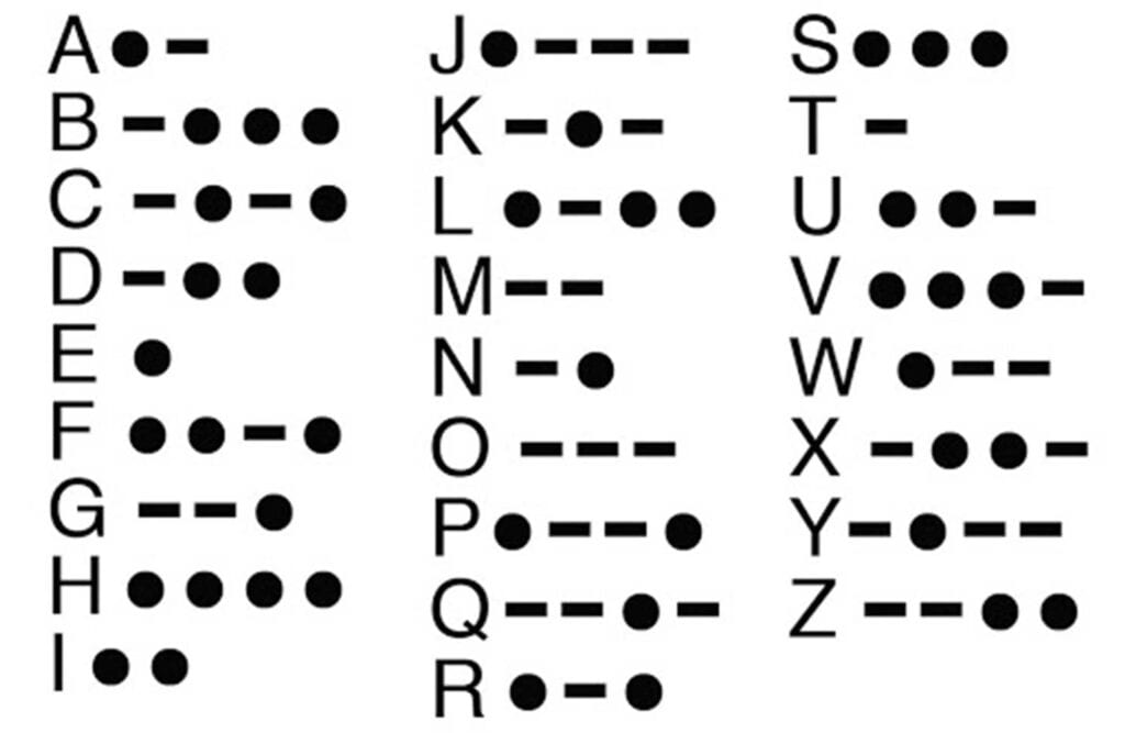
Using the morse code* chart below, choose a 4-letter secret word and send it to another team on the table next to you. Take advantage of the paddle’s switch long wires and don’t let them hear your secret word! In turns, you will need to decode each other’s secret word to succeed.

* Morse code is a method used in telecommunications to encode text characters as standardized sequences of two different signal durations, called dots and dashes, or dots (1 unit of time) and dash (3 units of time).

* Morse code is a method used in telecommunications to encode text characters as standardized sequences of two different signal durations, called dots and dashes, or dots (1 unit of time) and dash (3 units of time).


Documentation:

For your documentation, create a blog post that includes the following items based on your experience in this recitation. Include all of these elements in your documentation:

For each of the three steps in Task 1:

    • Write what the circuit does, and some observations on how the components accomplish this.
    • Include pictures and or videos of the completed circuit working
    • Describe the process of building the circuit: Did the circuit work? Were there any moments where something failed? How did you solve the problem? Write down what worked and what didn’t. What was the process of working with  your partner?

For Task 2:

    • Describe your process in task 2, highlighting things you learned, any difficulties you had, any comments about what you made and how you made it. Include a photo.

For Task 3:

    • Describe what you did in task 3, and how you worked with your partner. Include relevant photos or videos.

Additional Required Questions: Take time to reflect on this week’s readings and the recitation exercise to answer these questions:

    • Question 1: What is the function of the resistor R1? (You can read about the reason why LEDs need resistors here) 
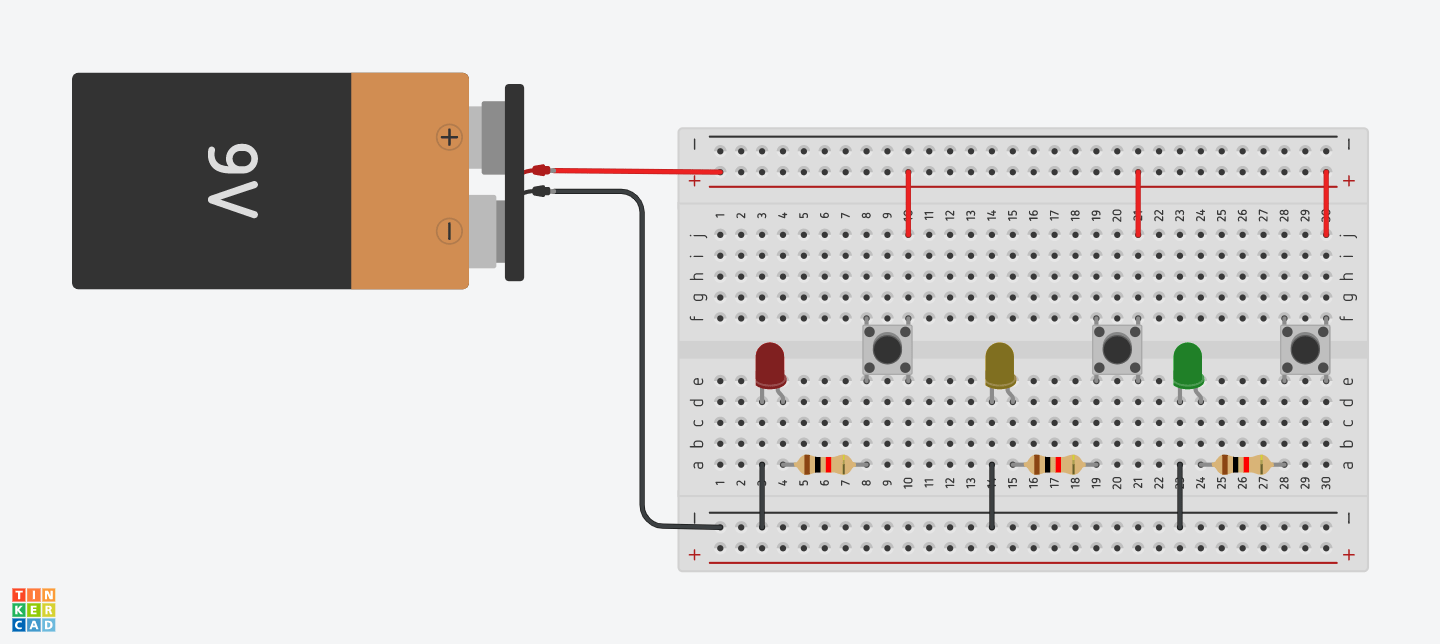
    • Question 2:  Looking at the following circuit, draw its diagram by yourself.

circuit with 3 buttons and 3 LEDs

    • Question 3: After reading The Art of Interactive Design, in what way do you think that the circuit you built today includes interactivity? Which degree of interactivity does it possess? Please explain your answer.
    • Question 4: How can Interaction Design and Physical Computing be used to create Interactive Art? You can reference Zack Lieberman’s video or any other artists that you know.

Reference: Components and Diagrams

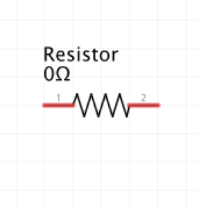
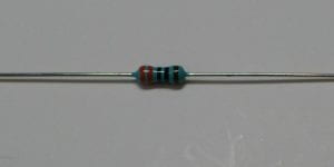
Resistor:

Resistor symbol

Image from Techversat.com

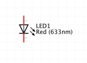
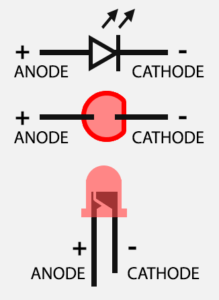
LED:

LED symbol

Image from Tweaking4All.com


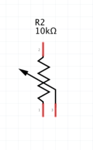
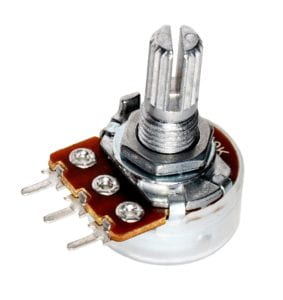
 Potentiometer (POT) /Variable Resistor:

Potentiometer / variable resistor symbol

Image from Hellasdigital.com
Image from hellasdigital.com

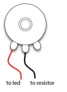
Potentiometer pinout

Push Button (Switch):

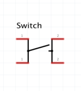
Push button / switch symbol

Image from Razzpisample


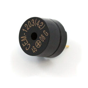
Speaker (Buzzer):

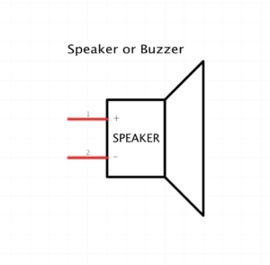
Speaker / buzzer symbol

Image from Sparkfun.com

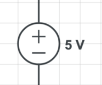
Power: 

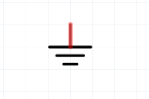
Ground (GND) symbol


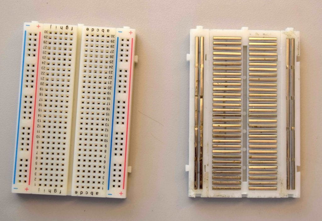
Breadboard:

breadboard side by side

The breadboard has wires inside of it. You can read more about it in the article Making prototype circuits using a solderless breadboard. You can see the pattern if you remove the adhesive paper from the back of the breadboard. But don’t remove it completely – The wires might fall out!