Recitation
Instructions:
In this recitation, you will build three circuits: Circuit 1: Fade, Circuit 2: toneMelody, and Circuit 3: Speed Game and run them using the example code. Document your process making them, as well as each of the assembled circuits.
Materials:
- 1 * Arduino Uno
- 1 * USB A to B cable
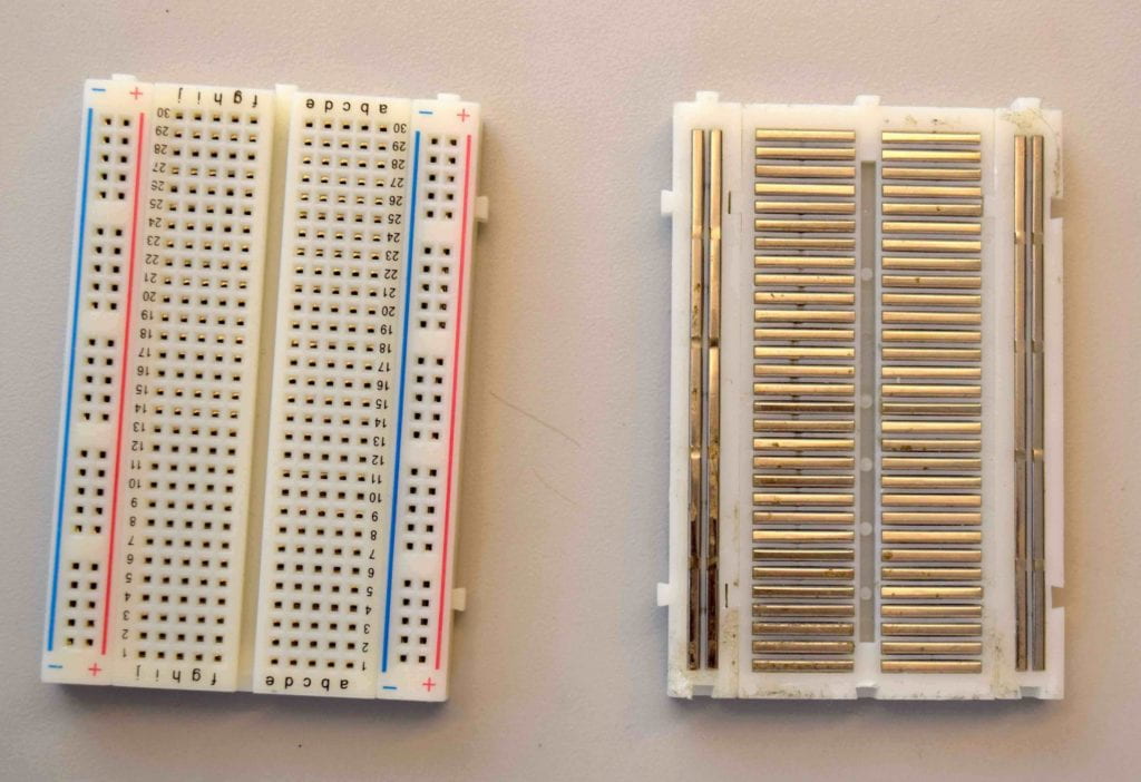
- 1 * Breadboard
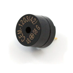
- 1 * Buzzer
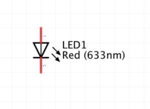
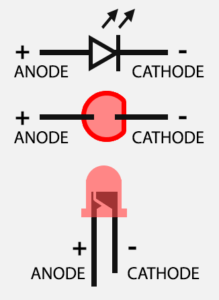
- 2 * LEDs
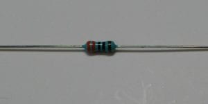
- 2 * 220 Ohm resistors
- 2 * 10 kOhm resistors
- 2 * Pushbuttons
- A handful of jumper cables
From the Cart (optional, only if you need them):
- 1 or more * DIY paddles (cardboard buttons from Recitation 1)
- 1 * Multimeter
- 1 * USB-C adapter (You should purchase your own after this recitation if you need one. Some don’t work well with Arduino, but ours do. We bought them here.)
Circuit 1: Fade
Work individually to build the “circuit 1: Fade” following the circuit-building part of the instructions here: https://docs.arduino.cc/built-in-examples/basics/Fade. When you finish building, access the code from Arduino IDE > File > Examples > 03.Analog > Fading and upload it to your Arduino.
Circuit 2: toneMelody
Work individually to build the “circuit 2: toneMelody” following the circuit-building part of the instructions here: https://docs.arduino.cc/built-in-examples/digital/toneMelody. When you finish building it, access the code from Arduino IDE > File > Examples > 02.Digital > toneMelody and upload it to your Arduino.
Circuit 3: Speed Game
This is a two-player game where each participant races to click a button more quickly than their opponent. Whoever has clicked their button ten times the fastest wins!
This circuit is provided as a layout diagram instead of a schematic, so as part of your submission for this recitation, draw your own schematic of how the components are connected.
To build the game, work in pairs:
1. Sign in with your Tinkercad account, or sign up if you don’t have one yet. (Please remember your login since you will also use it for the rest of the semester.)
2. Open the Speed Game Example. Click “Copy and Tinker” to view the layout diagram and code.
3. Connect the circuit accordingly and copy the code into your Arduino IDE. Run the program.
/* Tips:
   1. In Tinkercad, you can click on an electronic
   component to view its name and parameters (for example,
   resistor, value: 220).
   2. Click the "Code" button to view the code.
*/
4. To play the game, first open up the Serial Monitor in the Arduino IDE for instructions. To start the game over, press the Reset button (the little red one!) on your Arduino Board.
Document you and your partner interacting with the circuit. If you have extra time, here are two optional steps:
1. Switch out the pushbuttons with the DIY paddles you soldered during the previous recitation.
2. Find another group and combine your circuits to make a four-player speed game.
Documentation
Please post your responses to the 3 questions below, along with the other documentation for the circuits that you built. Don’t forget to include an explanation of your process of building the circuits, how you solved any difficulties you encountered, and your own drawing of the schematic for circuit 3!
Question 1: Propose another kind of creative button you could use in Circuit 3 to make the game more interactive. Read and use some material from the Physical Computing, Introduction Chapter (p. xvii – p. xxix) to explain why this button would make this game more interactive.
Question 2: Why did we use a 10 kOhm resistor with each push button? (Psssst… Go back to your slides for this answer)
Question 3: In the book Getting Started with Arduino there is a clear description about the “Arduino Way” in chapter 2. Find a project that you find interesting that can be used as an example for these kind of projects. Cite it in adequate manner, include a picture, and explain the reasons that you chose it.


