This week, we will be creating a kinetic sculpture using digital fabrication tools.
Such sculptures use movement as their basic element to create works of art.

Image: Dimensions by David C. Roy
Step 1: Design
To make your own kinetic sculpture using digital fabrication methods you will first need to design your parts with computer-aided software (CAD). In this case, you will use cuttle.xyz which is a 2D vector software optimized for laser cutting. Watch the 4 mintue tutorial on cuttle!
Work together with a partner to build one sculpture. Each one of you will design half of the parts. At the end of the recitation you should end up with something like this:
Step 1.1: Stand design
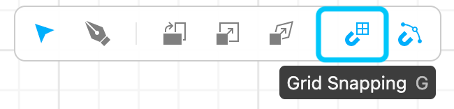
In cuttle, go to Units & Settings to change the inches into millimeters.
| Student A | Student B | |
| .
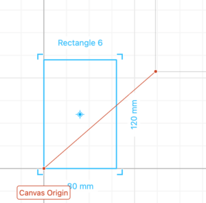
Start by creating a new document and activating the “Grid snapping” option in the toolbar at the top of your canvas. This will help you place components accurately on the grid.
Drag a rectangle a place it in the origin.
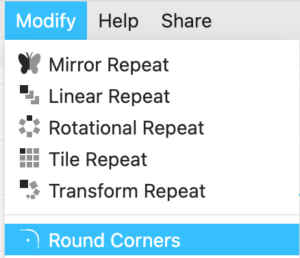
Select the rectangle and add a round corner modifier. Add a 3 mm radius rounded corner.
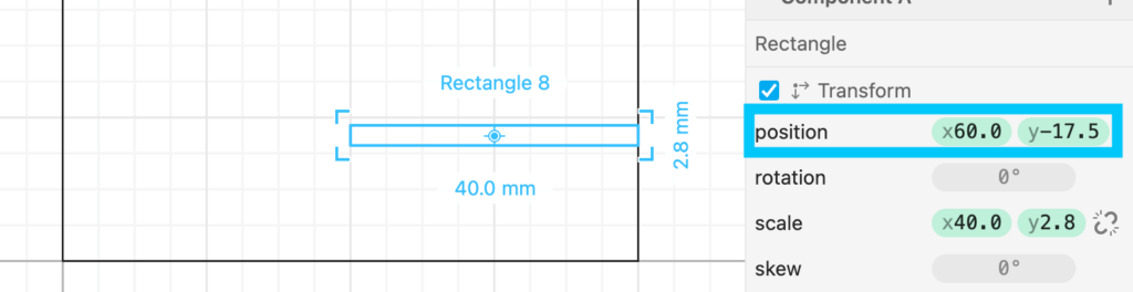
Drag another rectangle size 40 mm wide and 2.8 mm tall (2.8 mm is the thickness of the material we will cut). Place it on the right side edge of the first rectangle you placed and -17.5 mm on the Y axis. This rectangle will create a slot for 2 pieces of wood to intersect with each other and create the stand.
Select both rectangles and perform a “Boolean Difference”. This allows you to subtract one shape from another.
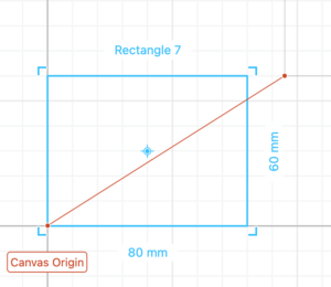
Drag and drop a rectangle based on the servo dimensions measured by your partner.
Drag and drop a circle based on the servo’s screw hole diameter. Adjust the position as shown in the gif below. Copy the hole to the other side.
Select all the lines of your design, right-click and select Group (⌘G / Ctrl+G) You have now finished the stand design. |
Start by creating a new document and activating the “Grid snapping” option in the toolbar at the top of your canvas. This will help you place components accurately on the grid.
Drag a rectangle a place it in the origin.
Select the rectangle and add a round corner modifier. Add a 3 mm radius rounded corner.
Drag another rectangle size 40 mm wide and 2.8 mm tall (2.8 mm is the thickness of the material we will cut). Place it on the right side edge of the first rectangle you placed and -17.5 mm on the Y axis. This rectangle will create a slot for 2 pieces of wood to intersect with each other and create the stand.
Select both rectangles and perform a “Boolean Difference”. This allows you to subtract one shape from another.
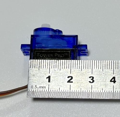
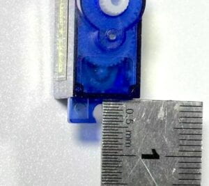
Measure the width and depth of the blue servo motor in your arduino kit.
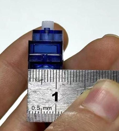
Measure the servo screw hole diameter and its distance from the inside edge.
You have now finished the stand design. |
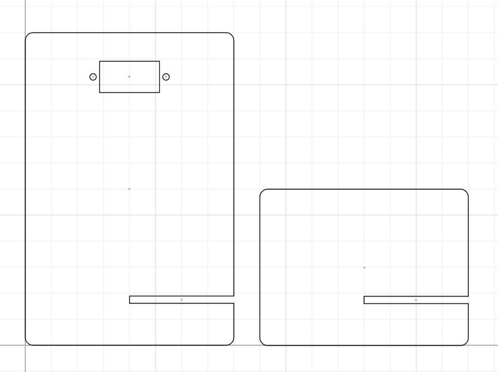
Together your design should look like this. After the second part of the design is completed, you will merge your files together.
Step 1.2: Pattern design
Here is where you get to be creative. Each one of you will design a pattern that when put together will create an interference visual effect. Same as you did during the cuttle.xyz intro tutorial, create a circular pattern of 120 mm in diameter. Feel free to experiment with the tools and shapes until you come up with something interesting.
For a more interesting effect, students A and B should design patterns going in opposite directions.
*Tip: Use the canvas origin point to easily create the circular pattern. If necessary move the previous objects away.
Here is a reminder of the commands used in the tutorial:
-
-
- Create a shape (try using 1 or multiple paths) ->
- Rotational repeat (the more repetition the better the effect) ->
- Outline stroke ->
- Select pattern, right-click, and Group (to make it easier to move around)
- Tip: You can use the Pen tool to create lines. You can make a curve with the handles of the pen.
-
Alright, you are almost done with the design. To finalize you need to find a way to mount the circular patterns.
-
-
- One of them will be attached to the stand and will be static with a square cut-out (32.5 x 12.5 mm) for the servo to go through.
- The other one will be attached to the shaft of the servo which will move it in a sweep motion. For that create a circle diameter 4.5 mm.
-
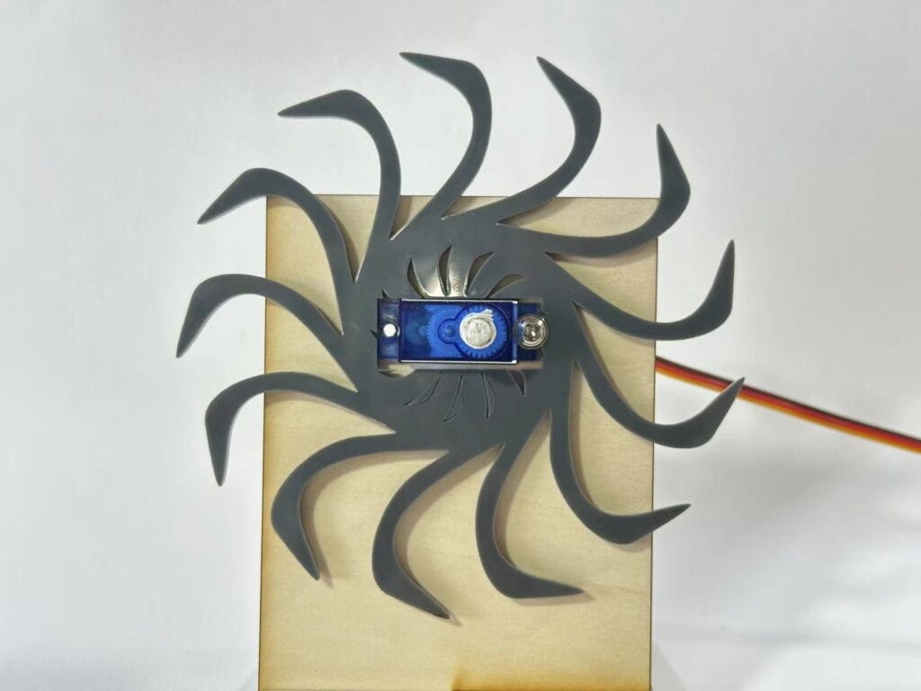
Decide who will make the moving/static part and add the additional features in your design that will allow you to mount your patterns. The implementation should look something like this:
Step 1.3: Export your design
-
-
-
- File -> Export SVG
- Create a new folder with your names in this Google Drive and add both of your files.
-
-
Step 2: Laser cut
Once you and your partner have finished Step 1, you can now laser cut your parts. For this recitation, you can just go directly to the fabrication lab in 823 but remember that you will need to
-
-
-
-
- Come to the front table to laser cut before the recitation ends.
- Come to Office Hours this Friday, November 25, at 3 pm to 823.
- Book an appointment on the fabrication lab website.
-
-
-
Step 3: Assemble
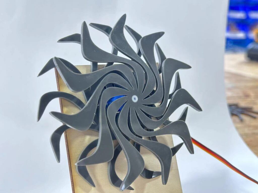
Assemble your stand with the servo and the circular patterns. You also may need to add a screw to keep everything together. Connect the servo wires to your Arduino with the File > examples > Servo > Sweep example. You should now be able to contemplate the result of both of your designs overlapping each other!
Documentation
Make sure you document the design and fabrication of the entire process.