Project title: Snowball
Leah Bian
Professor: Eric Parren
I. Context and Significance
In the group project, our team made a “painting machine” that could record a person’s day with body data. It was our first attempt to apply our personal definition of “interaction” into a physical thing. We implemented the idea of “input, processing and output” in the project, and tried to show the interactive process clearly. My definition of “interaction” also developed in that experience. In the individual reflection for the group project, I listed two projects that I researched online——OpenDataCam 2.0, and“Sharing Faces”. I wrote in my reflection that interaction should be separated into two parts: physical interaction and emotional interaction. Emotional interaction involves emotions, humanistic feelings and aesthetic value. In my opinion, high-level interactivity should combine these two parts of interaction organically.
Before I started working on my midterm project, I did some research online to further my understanding of “interaction”. Light Kinetics, a project created by Madrid based creative studio Espadaysantacruz, inspired me. It is an interactive light installation where the behavior of light is controlled by a physics simulator. According to the author Filip Visnjic, “the initial impulse is regulated by the strength of the tap, creating a very natural interaction. When one hits hard light moves fast and can overcome the force of gravity, when one hits the bulb softly light falls slowly along the top.” That is to say, the user’s behavior could directly affect the way that the device works. From my perspective, the biggest problem of some interactive devices is that the output is determined by a preset program, instead of being affected by the external behaviors. Therefore, a highly interactive device should allow the user to really engage in the interaction, instead of excluding them as the audience or actors.

II. Concept and Design
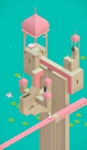
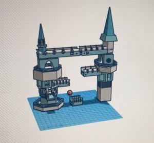
When we were still struggling with the brainstorming of the project, my partner Eric proposed that we could build a maze in which the LEDs along the path would bright up with the character in the maze moving. Then, an idea bumped into my mind that we can build a three-dimensional maze instead of one that is on a two-dimension plane. I thought of Monument Valley suddenly. It is an indie puzzle game developed and published by Ustwo Games. The player should discover the hidden paths, and lead the princess Ida (a game character) through mazes to various platforms, and the mazes are designed as castles. We decided to make the game real with 3D printing and Arduino. The project do not have an intended audience, since the game allow people of different ages to engage with.
At the beginning, we thought for a long time about what to use as a replacement for princess Ida in Monument valley. We wondered whether we could let the player complete the maze without using any characters, but it would lead to some problems. For example, without a character, the player cannot know whether the paths are connected correctly, and it would be hard to tell what is the correct order of connecting the paths. In addition, the goal of completing the game would be vague, and the player cannot gain a strong sense of accomplishment. Therefore, we raised our concerns and the IMA fellow Jingtian gave us some suggestions. She advised that we can use a small ball as the substitute, and the player can control the movement of the ball by shaking the KT board stuck to the bottom of the “castle”. This suggestion helped us a lot in developing the basic ideas and concepts.
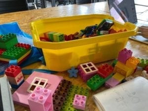
In addition, we thought for long about what materials to use to build the maze, since we were concerned that it would be too complicated to build the castle only with 3D printing. Then, we considered using cardboard and Lego. We looked up some information about cardboard craft online and went to a Lego stationary store to look for possible materials. However, we found that the cardboard was unstable and somewhat crude, and the types of Lego models were limited, making it difficult to fit the circuits that we need to install on the castle. Therefore, we finally decided that we would build the castle only with 3D printing. It was a challenge, but we were both excited about it.
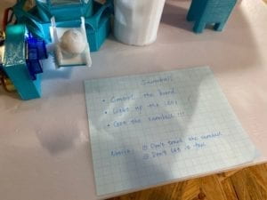
After we decided those basic ideas, we began to design the specific levels of the maze. We decided to make the maze consist of the following three parts:
- Control the two paths with buttons, let them turn 90 degrees respectively, then let the two ends of the paths meet.
- Let the small ball fall through the hole, hit the touching sensor, and then let the short path turn 90 degrees.
- Use the potentiometer to rotate the triangular prism.
Note: The paths will be stuck to the servos with hot glue.
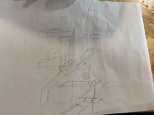
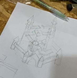
These are the two sketches that I drew as the plan during the development of ideas:
We also developed some other ideas for the game:
- The LED installed beside the button/sensor/potentiometer will bright up when the player has connected the paths correctly.
- The small ball will fall from the upper layer to the lower one though the holes.
- Half of a 3D-printed ball will be stuck to the board to help the player shake the board smoothly.
- The small ball will roll from the top layer to the KT board at the bottom.
III. Fabrication and Production
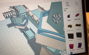
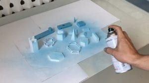
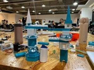
We started to work on the 3D printing part on Tinkercad with the sketches. At first, I was not skillful with it. But with the help of IMA fellows, I understood the basic process of 3D printing and reviewed those commonly used editing methods. We measured the sizes of the circuit components and designed our castle in its final form on Tinkercad. However, we did not realize that 3D printed objects need supporter. In our imagination, the final 3D printed castle should be printed in a complete way based on the model directly, and should be in the corresponding colors. But the reality is not like that, so we were quite surprised when told that we had to print all the components separately. It can be counted as our first failure in our first attempt at 3D printing, but it was a progress as well. After making some modifications to the model, we printed more than 20 components separately. Besides, to solve the problem of the insufficient supply of blue plastic, we sprayed some components into blue with sprayer cans, and found it quite interesting.
In the process of building the model, we came up with a delicate concept—— “snowball”. Since our castle is designed in the tone of white and light blue, and the small ball will roll from the top to the bottom, it fits the concept quite well. Therefore, we 3D printed a little white ball as our “snowball”.
In the Arduino part, we successfully let the code run. However, we found that the “snowball” that we printed was too light to be sensed by the touching sensor when it falls from the upper layer. Therefore, we used a glass ball as the substitute. We reprinted the paths that can fit the size of the glass ball, and painted the glass ball into white. But we were disappointed when we found that the glass ball could not trigger the touching sensor either, then we realized that it may be due to the problem of the contact surface, instead of the weight. We gave up this idea, and decided to let the player look for and press the touching sensor directly.
In addition, we started building the circuits with four Arduino Unos and four breadboards. However, we found that this seemed too cluttered and difficulties might exist in running the codes at the same time. Professor Parren suggested us to build the circuit on one larger breadboard and one Arduino Uno, so that we can make it simpler. We made it successfully, and solved the problem of running the four codes at the same time by putting them in one file.
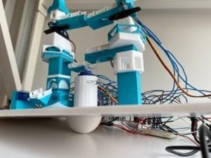
We were really lack of time before the user test. We barely managed to assemble all the printed parts together and successfully finished the programming of four circuits. We used solder to connect the LEDs, buttons and the breadboard together. However, we found that the space reserved in the 3D printed paths was too small to fit the LEDs and buttons in exactly the right place. In addition, since we only used one breadboard, the wires were intertwined. They were likely to touch each other or disconnect. These were the problems that we already discovered before the user test, but we did not have the time to solve.
On the user test day, only two of our four circuits could work normally due to the problems that I mention above. Therefore, we could only verbally describe the basic concepts and the game rules during the user test. Although it was a pity, we still received some valuable suggestions. For example, we can tie the wires together or stick them on the KT board to solve the problem of the tangled wires; write an instruction to make the game rules clearer; add a reset system to ensure a quick reset of the device for the next round…
We adopted these suggestions, and made the following adjustments:
- We reprinted the top two paths and moved the holes for the installation of LED and button to the side near the rotation axis, so that we can prevent the wires from being dragged by the path movement.
- We rebuilt the four circuits on four separate breadboards, that were originally placed on only one bread board, to alleviate the problem of the tangled wires and make them clearer visually for possible future adjustments.
- We wrote a simple yet implicit instruction to indicate the rule of the game for the players, while retaining the difficulty (let the player to explore).
- We built a reset system. Pressing a button at the end of a game can restore all four circuits at the same time.
- We installed a buzzer. When the player successfully connect all the paths, the automatic play of music will inform the end of the game.
We tested the circuits without the 3D printed components, and they worked well.
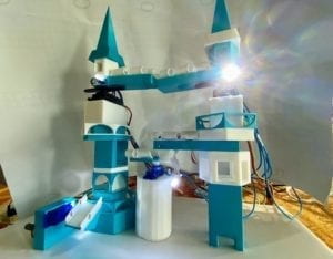
Final Version and Final Test:
IV. Conclusions
The goals of our project include: (1). Enabling players to actively seek solutions to solve the maze based on careful read instruction. (2). Let the user interact with our device by both physically controlling the KT board and exploring the hidden Arduino mechanism. Our project aligns with my definition of interaction well. It not only shows interaction on the physical level, but also reflects the aesthetic value. In addition, the output of our device is not based on the preset program, but is affected by the player’s operation and choice. While discovering the hidden buttons, sensors, and potentiometers, our players can also get a sense of surprise and accomplishment of mystery solving. On the presentation day, however, our assigned user had some difficulty in understanding the rules of the game. On the instruction note, I wrote “control the board”, but he misunderstood the board as the touching sensor, so we had to give a hint. This may be due to the reason that our instruction was a bit too vague, and it takes time to let the user understand the indication of the words we chose. In addition, Professor Parren suggested that we can hide the wires with some cloth or put them in the box since they looked messy. And we can add some handles on the KT board so that it will be clearer to the user that he can control the board. If we have more time, we will practice these two suggestions, and think more deeply about how we could retain the difficulty of the game, while making it easier for the user to understand how the whole thing works.
I have really learnt a lot from this experience. From my perspective, the most important part of the whole project is the initial concept and design, and secondly, how to make choices in every step of practice. Our personal definitions of “interaction” directly affects the conception of our project, and every choice we make should treat “interaction” as the priority. We should set high expectations of the final completion of the project at the beginning to ensure the expected highest quality. In real practice, even if some parts are sacrificed due to technical problems, the overall interaction of the device should not be weakened. We should view our project from the perspectives of the user and ask for suggestions, instead of blindly following our preexisting imagination of the concept. It helps us to find the problem, and reminds us to ensure the level of interaction. In addition, in the whole process, I also realized the value of meticulosity and accuracy. In 3D printing, one problem of measurement leads to the reprint of the whole thing. In programming, one character’s missing means the failure of the entire code. These details are the most essential parts that determine the success or failure of a project.
A video of the codes is attached below:
References:
OpenDataCam: https://www.creativeapplications.net/environment/opendatacam-2-0-an-open-source-tool-to-quantify-the-world/
Sharing Faces: https://www.creativeapplications.net/openframeworks/sharing-faces-seeing-yourself-reflected-in-the-image-of-others/
Light Kinetics: https://www.creativeapplications.net/processing/light-kinetics-interactive-light-using-a-physics-simulator/