Introduction
During week one recitation, we were introduced to circuits and the components that go into making them. We were provided schematics for three machines: a doorbell, a lamp, and a dimmable lamp. Prior to this recitation, the only previous experience I had with circuitry was from my high school physics class. Though I had a very basic understanding on how to complete a circuit, this was the first time I would actually construct one. If I am being completely honest, I was a little overwhelmed by the sheer amount of components that lay before me. Furthermore, the schematics we were provided looked more like alien drawings than anything. The only thing I really wished to learn was how to read all of the jargon and what all the components I was attaching to a breadboard actually did. Learning how to solder was also pretty fun. There really was no inspiration for this project since it was simply assigned to us, however it did show me concepts with which I could apply to future projects.
Circuit 1
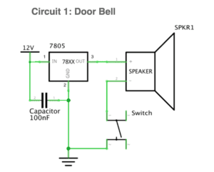
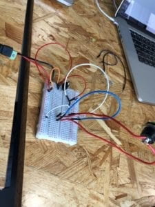
Here we have circuit 1, the doorbell. This was a relatively simple schematic to follow, however my lab partner and I both managed to screw this up many times. We would frequently connect wires to the wrong components. After help from a learning assistant, we were finally able to create our doorbell!
CIt was at this moment where we gave up reading the schematic and asked the learning assistant for help. After some much needed review on how to work a breadboard, we ended up with this…
Circuit 2
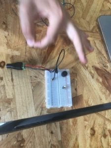
Circuit two was where things got really interesting. Midway through construction, we were called over to learn how to solder. We ended up using the arcade button pictured below as the switch for this circuit.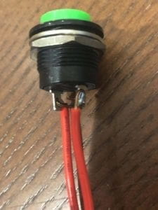
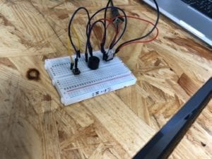
Before stating this circuit, my lab partner and I made the mistake of taking apart our entire circuit one, when in reality we could have utilized some of the existing wiring for circuit two. We were very angry after such a realization. There was one silver lining to this who situation. Upon asking a professor for help reconstructing our wiring, we learned that the capacitor can easily be implemented into the circuit by placing it right in front of the power supply as seen in the top left corner of the photograph. We ended up messing up once again and our circuit looked something like this…
You may notice that the circuit at first glance looks normal, and you would be correct. Turns out we did build the circuit properly, we just had a dead bulb. This showed us that even though I am new to this electrical wiring, I should have some confidence in myself.
Circuit 3
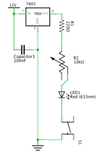
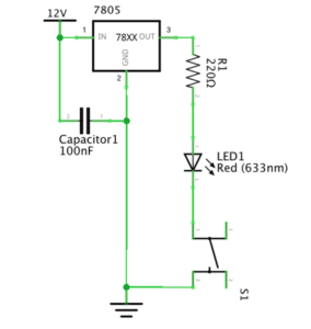
Starting circuit three was much better than circuit two since we didn’t lead off with ripping out all of the existing infrastructure. This one was not that hard to build since it was simply a matter of adding a dimming feature to the LED lamp that was possible through inserting a variable resistor into the circuit. Despite the simple task at hand, you guessed it, we messed up.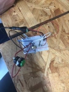
This issue here was a miswiring between the LED and the other resistor. We had the wires flipped around. Upon fixing the wires, we created this bad boy, and let me tell you, having built all this for the first time felt so good!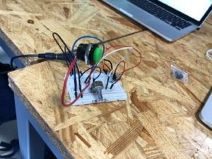
Reflection
Overall, the experience was a challenging yet rewarding one. Learning how to solder was great and it is a skill that I expect to frequently utilize throughout this semester. When it came to building the circuitry, it felt amazing to do this for the first time. Seeing those wires on the breadboard and being able to make sense of it all was a great feeling I’ll remember for a while. I look forward to expanding upon my skills and building bigger and better things.
Question 1
The circuits built in this recitation do display a level of interactivity. All circuits in this essay revolve around both input and output. Circuit one and circuit two utilize a simple switch for their input and use sound or light respectively as their output. Circuit three takes this one step further with the introduction of the variable resistor which takes the digital information of “on and off” and turns it into analog information by giving variation in the level of light emitting from the LED.
Question 2
Interaction design and Physical computing can be used to create interactive art in a plethora of ways. The main reason that comes to mind is the inclusion that interaction design brings to art. In my opinion, the quality of art is reflected in the impression it leaves on the beholder. If art contains a level of interaction with which the viewer is able to curate a unique experience, I feel like this makes the experience more memorable and thus validates the art as beautiful. Being able to have different expressions about what an art piece means because different people literally had different interactions with facilitates discussion and inspires others to push the bounds of how people can interact with what we originally thought to be stagnant.
very good documentation Kevin!
just copy/paste next time the questions before you answer, in that way anyone can understand what you are referring to.
You are missing documentation 2 and 3, please post them asap.