Exercise 1:
- Components:
1) an Arduino
2) a board
3) wires
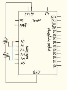
4) two potentiometers - Diagram:

- Codes:
1) Processing:
import processing.serial.*;String myString = null;Serial myPort;int NUM_OF_VALUES = 2;
int[] sensorValues;
void setup() {
size(500, 500);
background(0);
setupSerial();
}
void draw() {
updateSerial();
printArray(sensorValues);
background(0);
fill(255);
ellipse(sensorValues[1], sensorValues[0],50,50);
}
void setupSerial() {
printArray(Serial.list());
myPort = new Serial(this, Serial.list()[ 9 ], 9600);
myPort.clear();
// Throw out the first reading,
myString = myPort.readStringUntil( 10 );
myString = null;
sensorValues = new int[2];
}
void updateSerial() {
while (myPort.available() > 0) {
myString = myPort.readStringUntil( 10 );
if (myString != null) {
String[] serialInArray = split(trim(myString), “,”);
if (serialInArray.length == NUM_OF_VALUES) {
for (int i=0; i<serialInArray.length; i++) {
sensorValues[i] = int(serialInArray[i]);
}
}
}
}
}
2) Arduino:
void setup() {
Serial.begin(9600);
}
void loop() {
int sensor1 = analogRead(A0);
int sensor2 = analogRead(A1);
// keep this format
Serial.print(sensor1);
Serial.print(“,”);
Serial.print(sensor2);
Serial.println();
delay(100);
}
- Video of completed circuit:
- Reflections on the interaction: For this exercise, I use the potentiometers to control the movements of the ellipse. I think the interaction is a fairly good one since it breaks down the boundaries between the digital and physical world. I can see the huge potential of this basic interaction and how it can serve as a foundation for some high-quality interaction we are using in the contemporary world like those video games. Maybe this can be one inspiration for my final project.
Exercise 2
- Components:
1) an Arduino
2) a board
3) wires
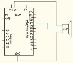
4) a buzzer - Diagram:

- Codes:
1) Processing:
import processing.serial.*;int NUM_OF_VALUES = 2;Serial myPort;
String myString;
int values[] = new int[NUM_OF_VALUES];
void setup() {
size(500, 500);
background(0);
printArray(Serial.list());
myPort = new Serial(this, Serial.list()[9], 9600);
myPort.clear();
myString = myPort.readStringUntil( 10 );
myString = null;
}
void draw() {
{
background(0);
values[0] = mouseX;
values[1] = mouseY;
}
sendSerialData();
echoSerialData(200);
}
void sendSerialData() {
String data = “”;
for (int i=0; i<values.length; i++) {
data += values[i];
if (i < values.length-1) {
data += “,”;
}
else {
data += “n”;
}
}
myPort.write(data);
}
void echoSerialData(int frequency) {
if (frameCount % frequency == 0) myPort.write(‘e’);
String incomingBytes = “”;
while (myPort.available() > 0) {
incomingBytes += char(myPort.read());
}
print( incomingBytes );
}
2) Arduino:
#define NUM_OF_VALUES 2
int tempValue = 0;
int valueIndex = 0;
int values[NUM_OF_VALUES];
void setup() {
Serial.begin(9600);
pinMode(9, OUTPUT);
}
void loop() {
getSerialData();
tone(9, values[0], values[1]);
}
void getSerialData() {
if (Serial.available()) {
char c = Serial.read();
switch (c) {
case ‘0’…’9′:
tempValue = tempValue * 10 + c – ‘0’;
break;
case ‘,’:
values[valueIndex] = tempValue;
tempValue = 0;
valueIndex++;
break;
values[valueIndex] = tempValue;
tempValue = 0;
valueIndex = 0;
break;
for (int i = 0; i < NUM_OF_VALUES; i++) {
Serial.print(values[i]);
if (i < NUM_OF_VALUES – 1) {
Serial.print(‘,’);
}
else {
Serial.println();
}
}
break;
}
}
}
- Videos of the completed circuit:
- Reflection on the interaction: the interaction of exercise 2 is in an opposite way of exercise 1, where the instructions of the digital world are the controller. When I was trying to write the proper code to achieve the requirement, I found out exercise 2 was more complicated than one even though the major difference between the two is simply the direction of the command. Thus, I understand the explicit distinction between the digital language and physical language. Digital language is made up by tons of logically organized and abstract short answers but physical language consists of a detailed continuity of descriptive sentences. Thus, the effective transformations require us to put a lot of effort.