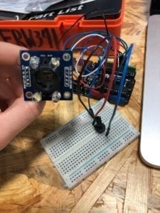
While in class we have used a potentiometer to control media we see on the screen, this recitation I tried to use a different sensor that will eventually be relevant to my final project.
Working with a Color Sensor!
Because I have never worked with this sensor before and it is totally new to me, I pretty much entirely copied the code from this website and used the explanation of how to use this sensor from this site:
https://randomnerdtutorials.com/arduino-color-sensor-tcs230-tcs3200/
For the most part this link was helpful in both the coding and the putting together of the Arduino components, however I encountered several difficulties not mentioned on this site. There are definitely challenges in reading different red, green, and blue values. It seems as if the blue colors are always very low, when compared with the others. I will most likely need to take this into consideration when I am working with this sensor in the future. Because I plan to use different colored tags, I will definitely need to plan to adjust the blue accordingly.
Arduino Code:
// TCS230 or TCS3200 pins wiring to Arduino
#define S0 4
#define S1 5
#define S2 6
#define S3 7
#define sensorOut 8
// Stores frequency read by the photodiodes
int redFrequency = 0;
int greenFrequency = 0;
int blueFrequency = 0;
void setup() {
// Setting the outputs
pinMode(S0, OUTPUT);
pinMode(S1, OUTPUT);
pinMode(S2, OUTPUT);
pinMode(S3, OUTPUT);
// Setting the sensorOut as an input
pinMode(sensorOut, INPUT);
// Setting frequency scaling to 20%
digitalWrite(S0,HIGH);
digitalWrite(S1,LOW);
// Begins serial communication
Serial.begin(9600);
}
void loop() {
// Setting RED (R) filtered photodiodes to be read
digitalWrite(S2,LOW);
digitalWrite(S3,LOW);
// Reading the output frequency
redFrequency = pulseIn(sensorOut, LOW);
// Printing the RED (R) value
//Serial.print(“R = “);
//Serial.print(redFrequency);
delay(100);
// Setting GREEN (G) filtered photodiodes to be read
digitalWrite(S2,HIGH);
digitalWrite(S3,HIGH);
// Reading the output frequency
greenFrequency = pulseIn(sensorOut, LOW);
// Printing the GREEN (G) value
//Serial.print(” G = “);
//Serial.print(greenFrequency);
delay(100);
// Setting BLUE (B) filtered photodiodes to be read
digitalWrite(S2,LOW);
digitalWrite(S3,HIGH);
// Reading the output frequency
blueFrequency = pulseIn(sensorOut, LOW);
// Printing the BLUE (B) value
//Serial.print(” B = “);
//Serial.println(blueFrequency);
delay(100);
Serial.print(redFrequency);
Serial.print(“,”); // put comma between sensor values
Serial.print(greenFrequency);
Serial.print(“,”);
Serial.print(blueFrequency);
Serial.println(); // add linefeed after sending the last sensor value
}
Processing:
In working on the processing code, I have selected photos that will most likely be relevant to my final project from this site:
https://unsplash.com/photos/amI09sbNZdE
And plan to switch between photos when the color sensor picks up on certain colored tags.
