Soldering
During the first recitation, we learned how to solder the wires and use this to create a simple circuit.
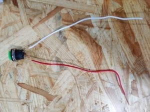
The first step in the process for my partner and I was soldering the wires in order to connect the doorbell to the simple circuit. We heated up the soldering device to about 300 degrees and then placed the wire on the heating device in order to create the solder. The way I understood it is the solder acts as a “glue” or activation site between the bell and simple circuit.
Circuits
The next step in the process was to build the circuit and we were able to successfully build diagram 1 and 2, and did not have time to start diagram 3. In the following are the materials we used, the diagrams, and an explanation of each:
Materials
- 1 * Breadboard
- 1 * LM7805 Voltage Regulator
- 1 * Buzzer
- 1 * Push-Button Switch
- 1 * Arcade Button
- 1 * 220 ohm Resistor
- 1 * 10K ohm Resistor
- 1 * 10K ohm Variable Resistor (Potentiometer)
- 1 * LED
- 1 * 100 nF (0.1uF) Capacitor
- 1 * 12 volt power supply
- 1 * Barrel Jack
- 1 * Multimeter
- Several Jumper Cables (Hook-up Wires)
Circuit 1: Doorbell
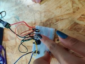
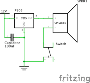
The first time my partner and I created the Doorbell circuit, we faced a few challenges. We understood that all circuits need to be grounded and all of the various wires and resistors should be connected somehow, but we did not realize that all of the materials needed to be connected on the same half of the breadboard in order to work. In addition, we understood that wire 3 should be connected to the speaker and wire 2 should be grounded, but we did not understand where to put wire 1. In our second attempt, we placed it to the power, and these changes made the circuit work.
Circuit 2: Lamp
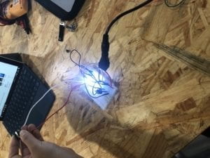
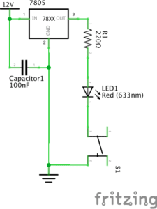
Our second circuit went much better than the first one because we knew to put all the materials on the same side of the breadboard. However, one of our issues at first was understanding which resistor contained 220 ohms. We ended up researching what different resistors looked like and found the correct one to use.
Question 1:
Interactivity in The Art of Interactive Design is defined in terms of a conversation: “a cyclic process in which two actors alternately listen, think, and speak.” The circuits we built today are interactive simply because all of the materials needed to work with one another. For example, the voltage regulator was connected to ground and so was the resistor, and in total, these all need to work with the electricity for the LED light to turn on.
Question 2:
Interaction design is essentially our creativity: this is the space where we create a product and think about how a person will use it. Physical Computing is used with interaction design in order to bring the project to life. Without physical computing, people themselves would have to “act out” or play the roles of each part of a circuit.