Introduction:
In recitation four, I created three different circuits with the addition of a stepper motor and a 12 VDC power source. The first circuit involved starting the motor with the help of an h-bridge to direct different forms of power and voltage from the Arduino. The second circuit carried the same base as the first, with the exception of an added potentiometer. The goal of this circuit was to control the movement of the motor rotor with the potentiometer. After working alone on the first two circuits, the goal of circuit three was to link up with a partner and create a joint drawing machine. This machine was powered by two motors that both my partner and I individually created in circuits one and two. My specific goals for this recitation were as follows: 1. To get through the recitation without short circuiting my Arduino board. This is imperative to my success and confidence in future recitations that I complete all circuits without misplacing a voltage or ground power source. 2. To safely complete the three circuits without any damage to myself or my partner. This has been a goal in all of my recitations, but especially with the 12 Volts being newly introduced today. 3. Lastly but not least, ask for help when I need it. In past recitations I had made a habit of trying to do it myself when I didn’t know something out of pride. But in these circumstances, I did not want a simple error lead to compromised safety for me or my partner. All resources used for this project were borrowed from the IMA lab in room 826/825 at NYU in Shanghai and also from my own Arduino kit handed out at the beginning of class. The materials used for this recitation are as follows:
For Steps 1 and 2
1 * 42STH33-0404AC stepper motor
1 * L293D ic chip
1 * power jack
1 * 12 VDC power supply
1 * Arduino kit and its contents
For Step 3
2 * Laser-cut short arms
2 * Laser-cut long arms
1* Laser-cut motor holder
2 * 3D printed motor coupling
5 * Paper Fasteners
1 * Pen that fits the laser-cut mechanisms
Paper
(Material list provided by NYU Shanghai IMA Department)
Circuit One
As I eluded to in my introduction, the goal for circuit one was to create a workable base for circuit two and three. This mean’t simply activating the stepper motor. In order to do so, I need four essential tools besides the Arduino and breadboard. These tools included a 12 Voltage power source to run the motor (because 5 Volts for the Arduino is not enough in this case), a stepper motor, a power jack, and a L293D ic chip (I will refer to it as an H-bridge throughout the rest of this documentation). In order to keep the wire clutter to a minimal, I first placed the H-bridge towards the bottom of the breadboard. This ensured that when I add the potentiometer in circuit two, there would be ample room to install the surrounding wires. Below is a picture of the planned circuit with the Arduino board on the left, the H-bridge in the center, and the stepper motor on the far right. All credit goes to NYU Shanghai for providing the diagram.
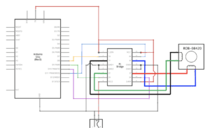
In order to facilitate ease when plugging wires into the power and 5 V sources, I linked a red wire from the positive column of the breadboard to the 5 V on the Arduino board. I also linked a black wire from the negative column of the breadboard to the ground power source on the Arduino board. What follows is a series of wire linkages from the 16 ports of the H-bridge to the Arduino board, the stepper motor, and 12 Volts power source. First, I linked port one (1,2 EN) with the positive column of the breadboard. I then linked port two (1A) to Digital 8 pin on the Arduino board. After, I matched a black wire from port three (1Y) to the black wire port (A) in the stepper motor. After, I matched ports four and five (GND 1 and GND 2) with the negative column to link them back to ground power on the Arduino board. I then linked port six (2A) with the green wire port (C) of the stepper motor. I followed this by linking port seven (2A) with digital pin ~9. To round off the left side, I connected the red wire (positive) of the 12 V source to port eight (VCC2) on the H-bridge. The next linkages start from the bottom right of the H-bridge. I connected port nine (3,4 EN) to the positive column in order to link it with 5 Volts of power. I then linked port ten (3A) to digital pin ~10. After, I linked port eleven (3Y) to the red wire port (B) of the stepper motor. I then reciprocated the linkages of ports four and five with ports twelve and thirteen with ground power (negative column). I then linked port fourteen (4Y) with the blue wire port (D) of the stepper motor, thus fulfilling all four ports of the stepper motor. Following this, I linked port fifteen (4A) with digital pin ~11 on the Arduino board. Lastly, I linked port sixteen (VCC1) with the positive column of the breadboard. It should also be noted that the black wire of the 12 V source was plugged into the negative column of the Arduino board to ensure access to the ground power. A picture of the completed circuit can be viewed below.
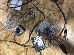
After completing the physical portion of the circuit, I inserted the example code from the Arduino website. All credit for the code goes to the Arduino website. In order to implement the code, I used stepper one revolution under examples. I then copy and pasted the code from the example in our recitation instructions. A copy of my code for circuit one can be found in the “My Code” section at the bottom of my documentation. Lastly, I plugged in the USB cord to my computer and uploaded the code to the Arduino board. The motor and code worked on the first try. A video of the completed circuit can be viewed below.
Circuit Two:
By using the base setup of circuit one, the goal for circuit two was to control the motor with a potentiometer. In order to do so, I had to insert a potentiometer and run the Motor Knob code provided by Arduino. I plugged the potentiometer into the upper middle part of the breadboard so that two prongs were on one side of the board and one prong was on the other side. I linked a wire from the back prong of the potentiometer to Analog zero (A0) on the Arduino board. I then linked a wire from the left prong of the potentiometer to ground power in the negative column. I also linked a wire from the right prong of the potentiometer to the positive column of the breadboard to ensure it was connected to 5 V of power. A picture of the setup with a potentiometer can be viewed below.
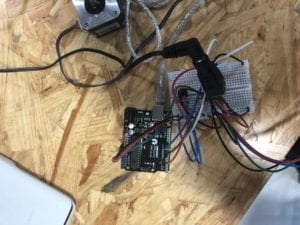
In order to run it properly, I used the code provided in the recitation instructions and copied and pasted Motor Knob into my Arduino browser. After doing so, I changed the steps defined from 100 to 200 and also inputed A0 to account for my analog port that the potentiometer was in. This ensured that I would be able to control the motor by moving the potentiometer. My code for Motor Knob can be viewed under the “My Code” section of my documentation. A video showing the movement of the completed circuit and stepper motor can be viewed below.
Circuit Three:
After laying the ground work by starting the stepper motor and a control for it, it was time to combine it with my partner Sarah and make a drawing machine. To do so, we used two laser cut shorts arms, two laser cut long arms, one laser cut motor holder, two 3D printed motor cut couplings, and five paper fasteners. We fastened both of our stepper motors into the cut out moldings to create stability for the other parts. We then both placed the 3D printed motor coupling on top of our stepper motor in order to create a base to use the short and long arms. We then each placed a laser cut long arm from our motor diagonally out so that they would cross.
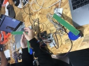
After, we placed fasteners from the long arms into the motor and fasteners from one long arm to the other. My partner and I then placed the short arms onto the ends of the long arms. They were positioned so that the ends of the short arms were criss-crossing. We then put fasteners into the intersection to stabilize the arms together. After, we inserted the pen into the hole at the end of each short arm. Following this, my partner and I positioned a piece of paper on top of my Arduino kit box to meet the pen. In order to activate the motors again, we used the same code Motor Knob from Arduino. Except below “void loop” we added Map and the corresponding values to link with potentiometer and motor. A full list of the code can be found in “My Code” at the bottom of my documentation. A video showcasing our joint stepper motor drawing machine can be viewed below.
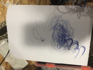
A picture of our finished artwork can be viewed below. We have decided to name it “The blue hills of Shanghai with a storm approaching.”
My Code:
Circuit one code:
/*
Stepper Motor Control – one revolution
This program drives a unipolar or bipolar stepper motor.
The motor is attached to digital pins 8 – 11 of the Arduino.
The motor should revolve one revolution in one direction, then
one revolution in the other direction.
Created 11 Mar. 2007
Modified 30 Nov. 2009
by Tom Igoe
*/
#include <Stepper.h>
const int stepsPerRevolution = 200; // change this to fit the number of steps per revolution
// for your motor
// initialize the stepper library on pins 8 through 11:
Stepper myStepper(stepsPerRevolution, 8, 9, 10, 11);
void setup() {
// set the speed at 60 rpm:
myStepper.setSpeed(60);
// initialize the serial port:
Serial.begin(9600);
}
void loop() {
// step one revolution in one direction:
Serial.println(“clockwise”);
myStepper.step(stepsPerRevolution);
delay(500);
// step one revolution in the other direction:
Serial.println(“counterclockwise”);
myStepper.step(-stepsPerRevolution);
delay(500);
}
Circuit two code:
/*
* MotorKnob
*
* A stepper motor follows the turns of a potentiometer
* (or other sensor) on analog input 0.
*
* http://www.arduino.cc/en/Reference/Stepper
* This example code is in the public domain.
*/
#include <Stepper.h>
// change this to the number of steps on your motor
#define STEPS 100
// create an instance of the stepper class, specifying
// the number of steps of the motor and the pins it’s
// attached to
Stepper stepper(STEPS, 8, 9, 10, 11);
// the previous reading from the analog input
int previous = 0;
void setup() {
// set the speed of the motor to 30 RPMs
stepper.setSpeed(30);
}
void loop() {
// get the sensor value
int val = analogRead(A0);
// move a number of steps equal to the change in the
// sensor reading
;stepper.step(val – previous);
// remember the previous value of the sensor
previous = val;
}
Circuit Three Code:
/*
* MotorKnob
*
* A stepper motor follows the turns of a potentiometer
* (or other sensor) on analog input 0.
*
* http://www.arduino.cc/en/Reference/Stepper
* This example code is in the public domain.
*/
#include <Stepper.h>
// change this to the number of steps on your motor
#define STEPS 200
// create an instance of the stepper class, specifying
// the number of steps of the motor and the pins it’s
// attached to
Stepper stepper(STEPS, 8, 9, 10, 11);
// the previous reading from the analog input
int previous = 0;
void setup() {
// set the speed of the motor to 30 RPMs
stepper.setSpeed(30);
}
void loop() {
// get the sensor value
int val = analogRead(A0);
val = map(val, 0, 1023, 0, 200)
// move a number of steps equal to the change in the
// sensor reading
;stepper.step(val – previous);
// remember the previous value of the sensor
previous = val;
}
Question One:
What kind of machines would you be interested in building? Add a reflection about the use of actuators, the digital manipulation of art, and the creative process to your blog post.
I think similar to this recitation, I would also be interested in making a machine that has to do with art. In the past year, I’ve been exposed to so much digital and interactive art that is has made me want to get involved. Although I still respect traditional artists such as Monet, interactive art has become so prevalent in our everyday lifestyle. Just yesterday, I was at the century avenue metro stop and I noticed four stationary bikes lined up in a row. I walked over and heard music also coming from the bikes. After watching, I realized that the power of the stationary pedaling provided different parts of the song. One bike provided the voice, while the other provided the beat. I think actuators are interesting because of their applicability in a project. By being the “middle man” that harnesses energy or a signal and then creates a movement, it works two jobs. The actuator is a focal point which the project hinges on for a dual purpose. I think the creative process can be extremely difficult in many ways. After examining many cases of digital manipulation, I was intimidated so say the least. Digital manipulation looks so incredibly difficult at times due to the copious amounts of resources used. But in reality, it may just come down to a singular sensor. So, I’ve encouraged myself to think big and build after rather than try and think through what would be easiest to build. This ensures that I have and continue to have creative control over my project.
Question Two:
Choose an art installation mentioned in the reading ART + Science NOW, Stephen Wilson (Kinetics chapter). Post your thoughts about it and make a comparison with the work you did during this recitation. How do you think that the artist selected those specific actuators for his project?
I have chosen to examine waves, by Daniel Palacios Jimenez (Stephen Wilson 117). I think this project is interesting in a multitude of ways but first and foremost because of how it incorporates audience movement. When there is a lot of movement, the rope moves at its quickest, producing movement and sound as a result. But when there is no movement, the rope parallels the silence by keeping still. It isn’t quite within the same realm as my own project, but I can compare the actuator to my potentiometer. In Waves, the rope moves and produces sound thanks to the actuator sensing movement from the audience. In my recitation, I a-liken the sound produced from the waves rope to the drawing produced by my drawing machine. Both the drawing and music have three step process’ where there is a movement (me moving the potentiometer or people moving in front of the rope), a translation by the actuator or Arduino, and finally a result of either music or a drawing.
Works Cited
https://wp.nyu.edu/shanghai-ima-interaction-lab/category/recitations/
(IMA Department Recitation Instructions)
https://www.arduino.cc/en/Tutorial/StepperOneRevolution
(Stepper One Revolution code)
https://www.arduino.cc/en/Tutorial/MotorKnob
(Motor Knob code)
https://drive.google.com/file/d/1MH0D7mTve4KQVn9FJ0KqXWa2TgGuJkPR/view
(Waves, by Daniel Palacio Jimenez)