Introduction:
In this recitation, we did soldering and built our own circuits according to circuit diagrams. My goals were: learn to solder skillfully and better my skills in reading circuit diagrams.
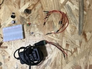
Materials(from the recitation instructions):
- 1 * Breadboard
- 1 * LM7805 Voltage Regulator
- 1 * Buzzer
- 1 * Push-Button Switch
- 1 * Arcade Button
- 1 * 220 ohm Resistor
- 1 * 10K ohm Resistor
- 1 * 10K ohm Variable Resistor (Potentiometer)
- 1 * LED
- 1 * 100 nF (0.1uF) Capacitor
- 1 * 12 volt power supply
- 1 * Barrel Jack
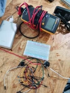
- 1 * Multimeter
- Several Jumper Cables (Hook-up Wires)
Soldering
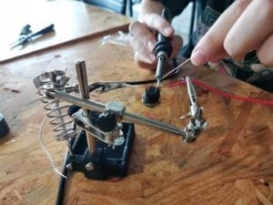
Melted tin can “glue” the wires and the switch together after it dries.
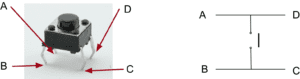
My partner and I used a soldering iron and a piece of soldering tin to connect two wires to a push-button switch. We first pealed the insulating layer on either ends of the two wires so the metal inside would be exposed. We then hooked one end of each wire onto the two iron bars on the back of the switch.
Following the instructor’s advice, we first used the soldering iron to heat up the connecting parts of the wires and the switch. Then we attached the soldering tin to those parts. The tin melted a little, but not quite in the way we hoped. (Maybe we used the tip of the soldering iron so the connecting part wasn’t thoroughly heated.) To accelerate its melting, we attached the soldering iron to the soldering tin.
We put the soldering iron there for such a long time that the plastic material of the switch melted! We took a new switch and tried again. This time we successfully connected the wires and the switch.
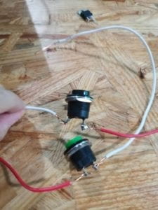
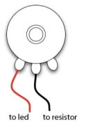
(The switch on top is the melted one)
Building our Circuits
Circuit 1: Door Bell
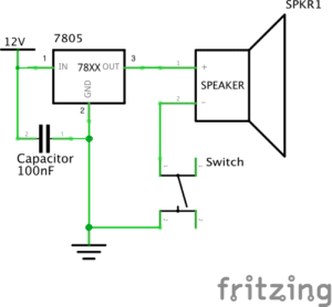
It was my first time to use a breadboard to build a circuit. It took me a while to actually understand how the holes on the breadboard were connected. Thanks to my partner’s patient explanation I finally understood how to imagine the “invisible” connections between different spots on a breadboard.
Tracing the lines on the circuit diagram, we quickly built a circuit. However it didn’t work because we were confused about how the wires can be connected to the “ground”. Our circuit didn’t work properly because it wasn’t a complete loop. Then we found out that the blue lines with a “-” symbol indicate where the wires connected to the “ground” should be put.
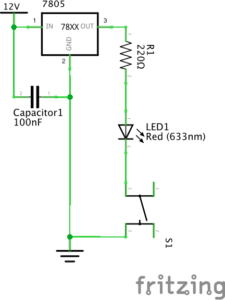
Circuit 2: Lamp

When we moved the wires, our circuit was short circuited. With the help of an instructor, we checked our circuit following the direction of the electrical current. Finally, the lamp lit up.
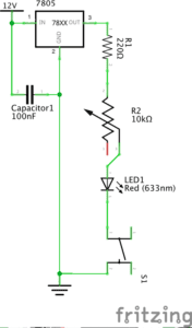
Circuit 3: Dimmable Lamp

We had become more experienced when building the third circuit. We built it with no difficulties.
Although the dimming wasn’t very obvious, it was actually dimmable. (We assume that maybe the maximum resistance of the variable resistor wasn’t enough)
Reflection
I learned how to solder in this recitation. Also, I learned how to properly handle tools with a high temperature (such as a soldering iron). Moreover, I learned to correspond an abstract circuit diagram with a real circuit.
However, I should also learn the lesson of accidentally melting the plastic part of the switch. Next time when I’m using an unfamiliar equipment, I should continuously check if everything is going well.
Question 1:
As the author says, interaction is a cyclic process in which two actors alternately listen, think, and speak. For the circuit, input, or “listen”, is the on and off of the switch(or the changes in the resistance of the variable resistor). Process, or “think”, may be the process that the electric current passes through the wires. Output, or “speak”, is the ringing of the doorbell (or the lighting/dimming of the LED). For us, we listen to the ringing of the bell, think about the proper moment to turn it off and, when we finally made our decision, we “speak” by actually using our hands to turn off the switch.
Question 2: Interactive design and physical computing are both indispensable in creating interactive art. Physical computing actually performs the processing part. Without it, interactive art would not come to reality. Interactive design makes possible the communications between people and interactive devices.