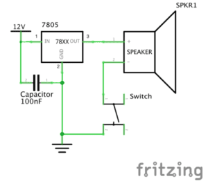
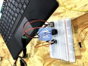
This is our first circuit–the doorbell circuit. It includes the power, a capacitor of 100nf, a voltage regulator, the bell, the switch and the breadboard. First thing that confused a lot was the way to use the breadboard. It took us a while to figure out how to use it. After that, everything work well.
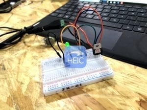
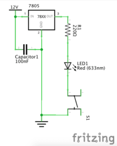
This is our second circuit, the LED circuit. It includes capacitor, voltage regulator, a resistor of 220 oum, an LED and a switch. The process went on quite fluently.
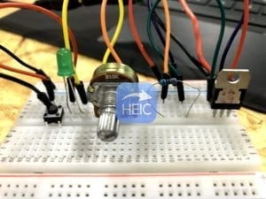
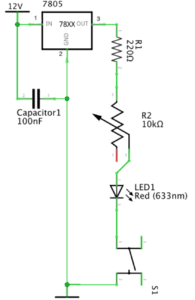
This is our third circuit, it includes one more variable resistor compare to the former circuit. At first, the circuit didn’t work well, however, we then found out that it was the problem of the switch and the variable resistor, we then try to adjust them. At last, the LED lighted, but the light was really slight.
For the three circuits, they all include a capacitor,, and the usage of it is to store electrical power and then release it .It’s designed to add capacitance to a circuit. Besides, all of them include a voltage regulator, it’s used to adjust the voltage of the power to a voltage that is suitable for the appliances, since different electrical devices have different working voltage . For the variable resistor in circuit 3, it’s used to adjust the current flwing in the circuit in order to control the lightness of the LED.
Answer to the questions:
- I think the interactivity is invovled in the process of building the circuit. One example is that when we finished building it, the electrical appliances worked. The door bell rang and the LED shines. That is a way that the ciircuits provide us with feedback, or interact with us.
- The answer is quite clear to the question. Through interaction design and physical computing we can create much more complicated circuits and we can make use of different kinds of sensors and mini computer to make the circuits interactive. That’s the charm of technology.