Solder an Arcade Button
Before we finished the circuit 1, we learned how to solder an arcade Button. We first cut a piece of wire in half and stripped one end of each half of the wire. Then we had the button fixed, and melted an end of a piece of metal wire, dripping the melting metal to the connecting hole of the button. At last, we needed to connect the exposed end of the wire with the button by putting the exposed end in the melting metal and waiting till it cooled down. However, our last step did not go very well; we could not connect the wire with the button no matter how we tried. Thanks to our instructor’s help at last; the arcade button was made eventually. And one thing important is that he taught us that selecting the wire which needed to be connected with the button is also a skill: the kind of wire with a single piece of metal wire inside is easier to connect with the button, instead of the one we chose, which is with several thin pieces of metal wire inside.
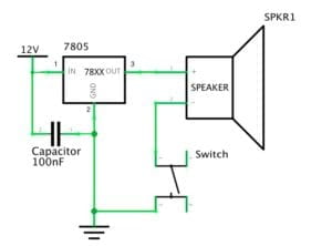
Circuit 1 – Door Bell
Components:
1* Breadboard: to offer a base where the circuit can be built on.
1* Voltage Regulator: regulate the voltage to the proper value of number that can serve the circuit.
1* 12-volt power supply: to get power from the patch board and provide 12V electrical power for the circuit.
1* Capacitor: to store and release the electrical energy.
A few hook-up wires: to interconnect the electronic components.
1* Buzzer: to serve as the “door bell”.
1* Push button (switch): to control the on-off of the door bell.
Diagram:
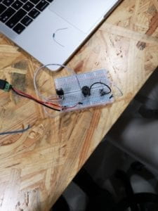
Picture:
Video:
Process:
Because the door bell was the first circuit I made with my partner, it was also the hardest one. We encountered a lot of problems we have never met before. In the beginning, my partner and I had no idea of how the breadboard functions and how the electricity flows across all those holes. After first asked our assistant Eszter, we figured out how to connect the wires to the power supply and the ground. However, when we connected other electronic components to the breadboard, we made a mistake: we misunderstood the direction of electricity flowing across the breadboard. The direction of electricity should be transverse but we considered it as longitudinal. So we connected the wires to the wrong holes with the components. Thanks to Eszter; she corrected us again. After got all the wires on their right position, we tried to connect the patch board. The door bell rang, however, the switch didn’t work, which means the bell just kept ringing. We checked the circuit again and found that we put the switch in the wrong direction. It was hard to notice that the switch was not near to a cube but to a cuboid, and we must carefully distinguish its inputs and outputs. After corrected this mistake, we finally succeeded! My partner and I were both very excited.
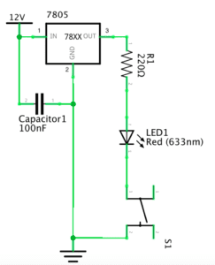
Circuit 2 – Lamp
1* Breadboard: to offer a base where the circuit can be built on.
1* Voltage Regulator: regulate the voltage to the proper value of number that can serve the circuit.
1 * 12-volt power supply: to get power from the patch board and provide 12V electrical power for the circuit.
1* Capacitor: to store and release the electrical energy.
A few hook-up wires: to interconnect the electronic components.
1* 220-ohm resistor: to reduce the voltage passing through the LED in order to avoid damage.
1* LED: to give the light after the electricity flows in.
1* Push button (switch): to control the on-off of the LED.
Diagram:
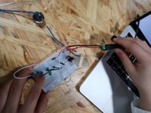
Picture:
Video:
Process:
The process of making circuit 2 was very smooth. My partner and I found the difference between the diagram of circuit 1 and circuit 2 was only to change the bell into the resistor and LED. So we kept the other electronic components on the breadboard; only removed the bell and connected the resistor and LED in. The process took less than one minute and we succeeded.
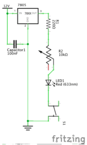
Circuit 3 – Dimmable lamp
Components:
1* Breadboard: to offer a base where the circuit can be built on.
1* Voltage Regulator: regulate the voltage to the proper value of number that can serve the circuit.
1 * 12-volt power supply: to get power from the patch board and provide 12V electrical power for the circuit.
1* Capacitor: to store and release the electrical energy.
A few hook-up wires: to interconnect the electronic components.
1* 10K ohm Variable Resistor (Potentiometer): to adjust the luminance of LED by adjusting the resistance, changing the voltage passes by the LED.
1* LED: to light up after the electricity flows in.
1* Push button (switch): to control the on-off of the LED.
Diagram:
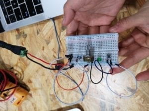
Picture:
Video:
Process:
Similar to circuit 2, we found there was only a little difference between circuit 3 and the last one. We switched the resistor in circuit 2 with the variable resistor and soon succeeded. Moreover, after we finished our work, I helped another group to check their circuit 3 and find the reason why it didn’t work. They connected the wire to a wrong hole so that it could not form a pathway for the electricity. After correcting the wire to the right hole, I was happy to see their work succeeded too.
Additionally, there was actually a non-standard operation made by me when I helped others. I corrected the circuit without powering it out. Such operations could be really dangerous and I’m sure I will pay much more attention to safety next time.
Question 1: After reading The Art of Interactive Design, in what way do you think that the circuits you built today include interactivity? Please explain your answer.
I think the interactivity represents in the responses of the circuits when we press the switch button. As the author states that interactivity is “in terms of a conversation: a cyclic process in which two actors alternately listen, think, and speak”, the circuits can be just considered to include these three elements. When we press the button, the circuit receives a signal; the process is just like the circuit is”listening” to our command. Then the electricity flows into the circuit and searches for a way out; this process is just like “thinking”. In the end, it makes a response, either lights up the LED or rings the bell. The response is similar to “speaking”. Therefore, with all three elements, I think the process that the circuits give responses when we press the button includes the interactivity.
Question 2: How can Interaction Design and Physical Computing be used to create Interactive Art? You can reference Zack Lieberman’s video or any other artist that you know.
I think Interaction Design and Physical Computing can be used to create Interactive Art by combining the design concept of an interactive artwork and the actual technology of achieving the concept together. In Zack Lieberman’s video, the eye-tracking technology provides a realistic basis for his artistic design, making the product come true. The two things together work out the successful interactive product Lieberman shows in the video. He inspires us that combining the Interaction Design and Physical Computing properly is one way that cannot be ignored during the development of Interactive Art.