Partner: Julia (Qianyue Fan)
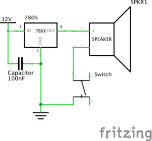
Circuit 1:
Breadboard: the platform for connecting the circuit
12-volt power supply: providing electricity for the circuit
Voltage Regulator: adjusting the voltage to make it close to the value needed by the circuit
Buzzer: a signal to show the circuit has electricity and is complete by making sounds
Push-Button Switch: controlling whether the current can go through, deciding whether the circuit is cut or not
Capacitor: storing electricity when the current goes in, and releasing energy when the circuit is without the current
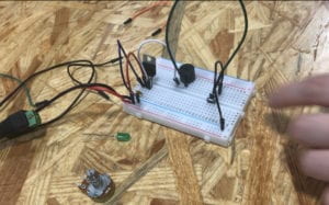
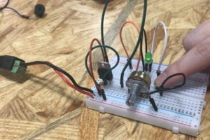
Building this circuit was really difficult for me since it was the first time that I had ever seen a breadboard. Therefore, we spent some time figuring out the function of each part of the breadboard. At first, we were confused about the voltage regulator, because we were not sure about the function of the three feet of it. With the help of the instruction, we set the voltage regulator correctly. Later, we did not know how to set the button, since it has 4 corners to be connected with 2 wires. With the help of an IMA fellow, we learned that we have to test which two corners to use by using a multimeter. Only if the number remains 0 can we use the tested 2 corners on the button, otherwise the LED would be on before pressing the button. Then we set the capacitor and finished this circuit.
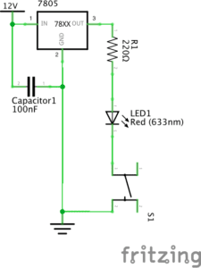
Circuit 2:
Breadboard: the platform for connecting the circuit
12-volt power supply: providing electricity for the circuit
Voltage Regulator: adjusting the voltage to make it close to the value needed by the circuit
LED: making sure that the electricity goes in a single direction, and showing whether the circuit is complete and correct or not
Push-Button Switch: controlling whether the current can go through, deciding whether the circuit is cut or not
220-ohm Resistor: limiting current to protect the circuit
Capacitor: storing electricity when the current goes in, and releasing energy when the circuit is without the current.
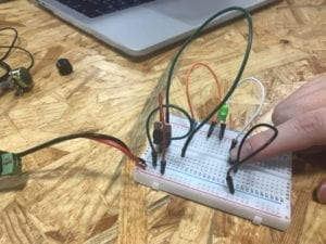
It was easier to build this circuit since we were kind of familiar with the breadboard. However, with too many components in the same circuit, it is hard to judge where to put the wires. At first, we thought our circuit was correct, but actually, we did not notice that there was a spare line connecting the capacitor and the power supply. Therefore, it is important to check whether all of the wires are necessary after building it.
Circuit 3
Breadboard: the platform for connecting the circuit
12-volt power supply: providing electricity for the circuit
Voltage Regulator: adjusting the voltage to make it close to the value needed by the circuit
LED: making sure that the electricity goes in a single direction, and showing whether the circuit is complete and correct or not
220-ohm Resistor: limiting current to protect the circuit
Variable Resistor: having adjustable resistance for the current
Push-Button Switch: controlling whether the current can go through, deciding whether the circuit is cut or not
Capacitor: storing electricity when the current goes in, and releasing energy when the circuit is without the current.
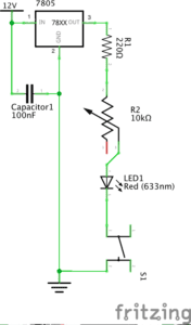
We finished this circuit quickly, because it was based on the previous circuit, and we only need to add a variable resistor. With the reminder of a fellow, we plug off the circuit to avoid getting shocked when making adjustments to the circuit. However, the circuit did not work even if it seemed correct. Later, we found out that we put the pins of the voltage regulator into the wrong holes, and we turned the variable resistor to its biggest value. After fixing these problems, the LED light was on.
Question 1:
After reading The Art of Interactive Design, in what way do you think that the circuits you built today include interactivity? Please explain your answer.
According to the reading, interactivity contains two actors, and they respond to each other’s action back and forth. For the circuits I built with my partner, the two actors are people and the circuit. When the circuit is completed, people get the signal that it can work, responding to it by pressing the button. The circuit responded to people’s action by letting electricity go throw, lightening the LED.
Question 2:
How can Interaction Design and Physical Computing be used to create Interactive Art? You can reference Zack Lieberman’s video or any other artist that you know.
Interaction Design and Physical Computing can be used to create Interactive Art, by building interaction between human body and computer. They exaggerate and concretize people’s inner incentive and emotion. A computer can react to the energy given off by bodies, and bodies can give different choices reacting to different signals given by the computer. According to Zack Lieberman’s project, Eye-writer, Interaction Design, and Physical Computing were used to help people who are not able to move to create arts. Therefore, Interaction Design and Physical Computing can be used to enable people who are unable to move to express themselves through a more convenient way, and concretize people’s inner feeling, artistic thoughts, and abstract emotion, by setting computers to react to and transform the energy given off by bodies.