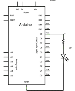
Circuit 1: Fade

Process:
- First, we put the LED light and the 220 ohm resistor on the breadboard. We also connected the shorter leg of the LED to the ground through a wire on the breadboard.
- Second, we used another wire to connect the ground rail on the breadboard to the ground pin on arduino board. We also used a wire to connect the button 5V pin to the breadboard, serving as a powersource.
- Then, we found the “fade” code from examples, connected the arduino board to my laptop, checked if we’ve chosen the right right port and board. We uploaded the “fade” code.
Result and learning:
- Result: The LED was originally on when we connected it to the 5V power source. When we uploaded the code to arduino, after a while, the LED started to fade regularly.
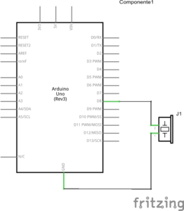
Circuit 2: toneMelody
Process:
- First, we put the buzzer on the breadboard.
- Second, we used a wire to connect the positive end of buzzer to upper pin 8, and a wire to connect the negative end of buzzer to upper pin ground.
- Third, we connected the arduino board to my laptop, uploaded the “toneMelody” example code
Result and learning:
- Result: the buzzer started to create its melody sound after uploading the code, as seen in the video below
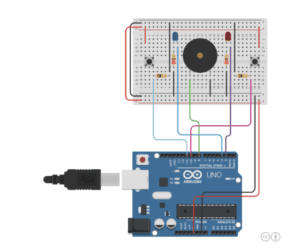
Circuit 3: Speed Game


Process:
- First, we placed two switches on the breadboard, respectively connected to two 10k ohm resistors.
- We placed two LED lights, respectively connected to two 220 ohm resistors through the breadboard.
- We placed a buzzer at the center of the breadboard
- Then, we used wires to connect the arduino 5V power source pin to the breadboard and another wire connecting breadboard to the bottom ground pin, and connecting the positive rails on two sides.
- We used wire to connect pin 11 and pin 10 respectively to the two switches, and used two wires to connect the 10k resistors to the ground.
- We connected pin 3 and pin 2 respectively to the two LEDs, and then linking the two 220 ohm resistors to the ground, respectively.
- Then, we connected the arduino board to the laptop, and uploading the speed game code.
Result and learning:
- Result: We opened the serial monitor as we tested out the circuit. After we pressed the reset button, we saw on the serial board showing instruction about when to begin, by “Ready? Go”. My partner and I respectively pressed our buttons, as fast as we could. Eventually my partner won the game, with the LED lights turning on, the buzzer creating a melody, and the serial monitor showing both how many times we each pressed and the result of the game.
- Learning: I learned from professors that the 220 ohm resistor is connected to the LED to prevent the LED from breaking; the 10K ohm resistor is connected to the switch to give out signal. I also learned that the serial monitor allows us to check and monitor the interactive process. If any parts of the circuits goes wrong and we are not able to see from the appearance of the circuit, we can probably use the serial monitor to find out which part goes wrong.
Question 1:
Reflect how you use technology in your daily life and on the circuits you just built. Use the text Physical Computing and your own observations to define interaction.
The Physical Computing text argues that physical computing creates an interaction and dialogue between the physical and virtual world. Similar as what’s stated in the article about interactivity, the authors of the Physical Computing text argues that interaction is an iterative process that involves listening, thinking, and listening of two actors. The interaction between human and computer involves how humans give out signals (inputs), how computers listen and think (processing), and how computer speak out with computational outputs.
In my everyday life, my interaction with my laptop is the most salient example of human-computer interaction. When I press certain keys on my laptop, my computer receives my inputs, it thinks about/processes what information I gives out, and then it speaks with media output such as letters showing up on my computer screen.
The circuit of fade LED light we built on the second recitation also involves such an interaction. As I upload the arduino code to my arduino board, the device receives my message and listens; it thinks about what command or messages I have sent out, telling it to control the fading of a LED light. Then it speaks out with the output, which controls the LED to fade regularly.
Question 2:
If you have 100,000 LEDs of any brightness and color at your disposal, what would you make and where would you put it?
If I have 100,000 of such LEDs, I want to create a giant installation that creates interaction between human emotions and the LED lights. When an audience stands in front of the installation, their facial expression and body movements will be captured by sensors and video cameras. If sensors detect an audience to be in happy mood, the LED lights will light up in warm colors and configure the shape of a smiley face. If the the audience was sensed to be in a bad mood, the LEDs will change into cold colors and create the shape of a sad face.
I want to place this installation at an enclosed space but located at a busy area of the city center, for instance, the West Nanjing Road in Shanghai or Time Square in New York. I hope the installation will help people take a break from the bustle and hustle of everyday city life, and become more mindful of one’s inner emotional state.