Overview
In the first week of class I learnt some basic theories about the electrics and made my first application during recitation. With my partner Sarah we built three circuits— a door bell, a lamp and dimmable light.
Materials and Functions
- 1 * Breadboard: Container for all components and has underlying wires for connection, both in horizontal and in vertical line
- 1 * LM7805 Voltage Regulator: Output adjustable voltage
- 1 * Buzzer: A speaker that outputs buzzing sound
- 1 * Push-Button Switch: Interrupt the flow of current
- 1 * Arcade Button: a sort of switch
- 1 * 220 ohm Resistor: Control the flow of current
- 1 * 10K ohm Resistor: Control the flow of current
- 1 * 10K ohm Variable Resistor (Potentiometer)
- 1 * LED: Lighting
- 1 * 100 nF (0.1uF) Capacitor: Stabilize the flow of current
- 1 * 12 volt power supply: Provide power for current flow
- 1 * Barrel Jack: Facilitate successful flow of current
- 1 * Multimeter: Measure electric properties such as voltage, current and resistance
- Several Jumper Cables (Hook-up Wires): Carrier of electricity.
Circuit 1: Door Bell
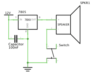
This is my first time building a circuit based on schematics. I spent some time to learn the symbols before starting to connect the wires.
Then I got confused by the wire connections when building the circuits. Everything seems interconnected. However, not that many external wires are needed. One reason is that the breadboard has inner wires. Another reason is that some components are already interconnected through other components. For example, there’s no wire between the voltage regulator and the capacitor because they are already connected through the wire that carries the current to the ground. I was also a little baffled about the order of building circuits.
I was also baffled by the order of building circuits at first. After consulting the fellow, I got to learn that normally people starts building from the anode all the way to the cathode, but order doesn’t order that much as long as you are familiar with the interconnections between electrical components.
What I learned and enjoyed most was building up circuits step by step according to the schematics. This was exciting because once it was done the breadboard was readable just like a tangible circuit. That somehow represents a transition from design to physical computing.
So finally it works!! Yah!!
Circuit 2: Lamp
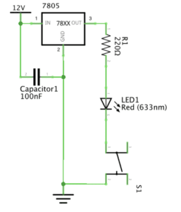
After overcoming the major difficulties experienced in building the first circuit, I got to become more familiar with the second one. I started from the scratch, but at a faster speed and with more clarity. The tricky part here, is the measurement of resistor. Just like what we often do when we have some questions, we googled the color match online and compared the color. Although this works, but it requires more energy and time. Later in class we learned that this can be measured through multimeter, which we forgot to use during practice!
Circuit 3: Dimmable Light
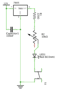
This one differs slightly from the second one in that it adds a variable resistor. And also since we were more familiar, so we didn’t pull out all the components and started all over again. We just built on what we had when building the second circuit. The tricky part about the variable resistor was the plugging in. Specifically, there were three foots on variable resistor with the same length with no signs of input and output. After asking the fellow we learned that the two foots on either side are constants and the middle one is the variable which means resistance can be altered here. So if you plug in the two sides then the flow will be constant whereas plugging in one side plus middle foot enables resistance changes. So we chose one side and middle foot to plug in. It works! The light is dimmable! This circuit brings more interactivity and therefore is more interesting!
Future Improvement
One thing I think can improve is to make the circuits on breadboard more readable and legible so that people would recognize that the circuit on the breadboard is exactly the one on the sketch paper. That will make our work and alterations to the work easier.
Responses to Questions:
1. After reading The Art of Interactive Design, in what way do you think that the circuits you built today include interactivity? Please explain your answer.
I think those simple circuits exhibit a “low level” of interactivity, according to the reading The Art of Interactive Design (6). As the author puts forward the definition of interaction: “a cyclic process in which two actors alternately listen, think and speak.” (5) The “listen, think and speak” corresponds to “input, process and output.” The three circuits we’ve built satisfy the requirements. Take the dimmable light for example. Every time I adjust the variable resistor the light will adjust its brightness accordingly. In this process I “input” a certain resistance, and the current “processes” the flow, and finally the brightness of light is “output.” However, since the process is quite simple as it just reacts directly to what I input, so the “degree of interactivity” is quite low.
2. How can Interaction Design and Physical Computing be used to create Interactive Art? You can reference Zack Lieberman’s video or any other artist that you know .
Interaction Design sets direction in which physical computing will follow. Design is the ideas that produce the theme of projects and physical computing is a practical implementation to reach the purpose of projects. Just as Zack Lieberman puts it, “artistic practice is a form of research.” Interaction design, as an idea, comes from daily observation and inspiration from others’ work or interaction. Physical computing, which involves software and hardware techniques, puts those ideas into practice by prototyping, testing and so on. Both are integral to realizing interactive art.