Tasks 1 and 2:
The goal of this project was to complete circuits to ring a doorbell (buzzer) and light an LED in different ways. This way, we gained a basic understanding of how circuits function, what to do, and what to avoid, such as short-circuiting.
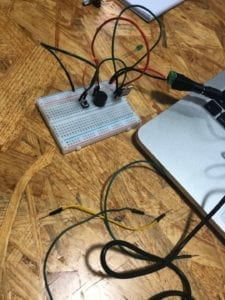
Below is an image of the first circuit we put together:

Included is a power source (supplying voltage) connected to a voltage regulator (to, well, regulate the voltage to the required amount). A capacitor is connected to the voltage regulator to store voltage. The speaker is wired to the third leg of the voltage regulator, which is in turn connected to a button. From there it is connected to ground, along with the second leg of the voltage regulator. Components are held in place and connected by a breadboard.
Below are linked videos of the functioning doorbell, LED and dimmable LED circuits. The third video includes our own soldered button.
(Diagrams were already given to us for this recitation, so we decided not to include them in the post.)
In these circuits, the basics stayed the same (power source, capacitor, voltage regulator, and switch), but the speaker was replaced by an LED. Furthermore, a 220-ohm resistor was used to limit the voltage the LED received. In the dimmable LED circuit a 10k-ohm variable resistor was used, allowing us to vary the amount of resistance, thus dimming or amplifying the light output.
Difficulties: For someone who has never touched a circuit before, the beginning was quite challenging. Connecting the capacitor to the voltage regulator took some time, but the diagrams helped greatly. The original button we used was also hard to understand. We were not aware that A/D and B/C were connected, but not to each other. A few times, our wires were not properly connected to the breadboard, causing us to think there was a complex problem while in fact we just needed to push the wires farther in. Other then that, everything went smoothly, soldering included.
Reflection: Our project went exactly as planned with minor issues that we quickly solved. Building circuits gave me general, practical knowledge of how all the components work, but I still could not build one on my own without a directional diagram. I hope by repetition I can learn to understand how to build my own circuits for personal projects.
Question 1: The author uses the terms, “listen, think and speak” to help define the word interaction. Take the LED circuit for instance: I press the button. The circuit “listens” processes what I asked it to do (with electricity) and “speaks” by illuminating the LED. I, seeing that the light is now on (listening), now want the light off (thinking), so stop pressing the button (speaking).
But, I would argue that the interaction is minimal, based on the author’s definition. I can interact with the circuit, but it does send me instructions the same way I send it instructions. In this example, the circuit has no way of making me remove my finger from the button.
Question 2: The fundamental part of interaction design and physical computing is that we can use it to make biologically non-living things react to our actions. The eye-tracking art feature in Lieberman’s video does just that. Another example is the wiring that allowed the reflective wood panel mirror to move in conjunction with a human’s movements to reflect light in the shape of what is in front of it.