Author: Tiana Lui, Class: Interaction Lab, Professor Cossovich
2.15.19
Components of the circuits: what they do and why are they included
1 * Breadboard- this is where the circuit is connected by wires. The breadboard connects components of a circuit together. A completely connected circuit is necessary for the circuit to work.
1 * LM7805 Voltage Regulator- Voltage regulators maintain a constant voltage level. They are important because many electronic devices only work properly within a certain range of voltage, and voltage regulators can make sure the voltage supplied in the circuit stays within that optimal range.
1 * Buzzer- A buzzer is an electrical device that converts one type of power to audible sound.
1 * Push-Button Switch- Switches are a control that can be used to interrupt the flow of current through a circuit. A pair of contacts within the switch are connected or disconnected depending on the physical position of the switch. When connected, the circuit is complete, and can execute tasks. When disconnected, the circuit is unattached, and the electronics do not execute anything.
1 * Arcade Button- Another type of switch.
1 * 220 ohm Resistor- A resistor is a two-terminal electrical component that resists the flow of electricity, and can be used to control the flow of current.
Resistors are marked with a series of colored stripes which indicate their amount of resistance.
1 * LED- Light-emitting diodes are a type of diode which can act as a visible or invisible light source. They are frequently used as indicator lamps in many electronic devices, or collectively as a display.
1 * 100 nF (0.1uF) Capacitor- Capacitors store electricity while current is flowing into them, then release the energy when the incoming current is removed. Capacitors can also be used to stabilize and smooth the flow of electricity.
1 * 10K ohm Variable Resistor (Potentiometer)- A resistor with the ability to change and control how much resistance to electrical current that programmer wants.
1 * 12 volt power supply- The power supply provides the power for the circuit to conduct electricity.
1 * Barrel Jack- Barrel jacks are electrical power connectors used for attaching extra-low voltage devices such as consumer electronics to external electricity. This is needed because we need a way to connect our circuit to power in order for there to be electricity/power to make the circuit run.
1 * Multimeter- Multimeters can measure the current, voltage, and resistance of objects. They are useful for identifying the correct components with the correct current, voltage, and resistances to place into your circuit.
Several Jumper Cables (Hook-up Wires)- Wires connect the circuit together. Without wires, electronic components are detached and the circuit is unable to work, because only a completely connected circuit will work.
Diagrams of the circuits
Below are the schematics of the circuits we built. The first one is a doorbell circuit, the second is a circuit of an led lamp, and the final circuit is a dimmable lamp circuit.


My notes
This was the first class we used the breadboard.
Initially, the breadboard was confusing to use, because we didn’t know what wires went where.
The picture of how the breadboard works helped us (the breadboard is composed of two strips of metal on the side and rows of metal on the inside).
We found out how to translate the circuit drawing to the breadboard.
So, to translate drawing to circuit, identify power source (12v this time).
Tip: keep power source wires on the side of breadboard (on the two vertical metal strips)
In this case, power source has two wires, one for power and one for ground
Continue connecting things to those immediately next to it in the drawing
If in the drawing, something is next to ground, connect component to ground on breadboard.
If in the drawing, something is adjacent to both power source and ground, connect component to both ground and power source.
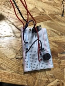
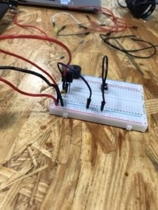
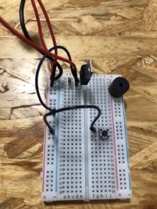
Voltage regulator had a 3 pins, and the order in which it was connected to other components mattered. The way to distinguish the pins is to understand that the bulky part (package) was the front. Knowing this made it easy to identify the order of the pins that corresponded to the drawing.
Keep the capacitor close to the voltage regulator. For some reason, the circuit will work better this way. Why?
Make sure the buzzer is in line with your wires. The buzzer is bulky and bigger than the width of the pins you input, so make sure to check that you put your wires next to the pins.
Tip: keep the buzzer slightly tilted/not all the way in to double check the positionings of its pins so you can accurately place wires next to those pins
There are different ohm resistors. You can check their color codes or use the multimeter to measure their ohms. 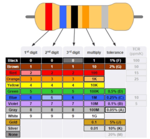
The multimeter reading didn’t work for us as the number kept jumping around. Need to understand how to properly get a multimeter reading. Also need to keep in mind conversions between units (ie. ohms and kiloohms)
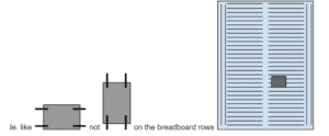
The switch has an orientation. It should be placed horizontally, (longer side connects on same row)
Unplug the power source every time before you move wires around, otherwise components can get fried and damaged.
We were only able to complete 2 circuits. We didn’t test out the push button we soldered.
Soldering (pretty straightforward)
There’s a machine that controls the temp of pen and makes a pen super hot, a stand for your soldering pen which has a cleaning sponge to clean the pen, metal wire you melt onto the two things you want to connect, a wire stripper, wire cutter…
The pen thing just gets really hot so you can melt metal.
Always clean pen (stab it on the sponge) to preserve its longevity and prevent rust.
A good solder is even and connects the two places you want to connect
Strip a bit of the end of wire, connect it to other part, solder by melting wire with pen, the melted metal should touch both exposed wire and other part.
Don’t breathe in fumes, they are toxic
Aren’t we supposed to have masks and some sort of vent/fan that captures/draws away the toxins???
Other advice
Most times, if circuit is good, double check the position of your capacitor?
Pictures and Video Captures
LED lamp circuit
Question 1:
After reading The Art of Interactive Design, in what way do you think that the circuits you built today include interactivity? Please explain your answer.
According to The Art of Interactive Design (Crawford), there are low and high levels of interaction. Since the circuits we built on Friday were relatively simple and only performed one task upon execution/under our influence, the circuits could be considered low-level interaction. However, the code and time required to build these circuits are much more complicating, and so our interaction with the circuits are relatively high and long. It is very challenging to define whether something is interactive or not, as there is no consensus on the scope of interaction. Does opening the refrigerator count as interaction, or does it count as talking to a brick wall? Does interaction only count when there is feedback both ways? And what type of feedback is qualified to be “interactive”? These are questions that need to be answered first before anything can be defined as interactive or not.
That said, the circuits we built on Friday, have various instances of interaction. For example, a human finger (analog input) pressing a button, causing the circuit to connect and complete. Or, the breadboard circuit communicating with the computer/arduino software, causing the electronics to execute actions. We also interacted with the hardware, placing wires into the breadboard, however, in that moment, the breadboard was not attached to the computer, hence, the breadboard gave no feedback, and may not count as interaction. We also interacted amongst ourselves, communicating with each other on how best to build the circuit. Above are examples of interaction, where two things that came in contact with one another produced some sort of action or communication.
Question 2:
How can Interaction Design and Physical Computing be used to create Interactive Art? You can reference Zack Lieberman’s video or any other artist that you know.
Interaction is about two or more things connecting, and communicating something to each other or spurring some sort of action to be executed. Physical computing is great for interactive art because physical computing is about making an electronic device communicate with computer software to perform some sort of action, a process that is already interactive. Interactive art using physical computing is also scalable, in the sense that the programmer can start by programming a low-level interaction, then move on to coding more complex interactions, generating higher-level communication and engagement between the computer, user, and artwork.
Physical computing can be combined with any type of interest to form an interdisciplinary study, so it is not unusual that physical computing is combined with art. One such artist, Zach Lieberman uses interactive media to explore the relationships between technology, performance, and the body. He has created projects including an open-source eye-tracking system that allows disabled artists to draw using their eyes, and a performance that includes drawn sketches that react to a visitors’ touch.
In summary, the world is your oyster. It is up to your imagination to use physical computing to create interactive art.
