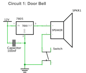
Circuit 1: Door Bell
Components:
1 * LM7805 Voltage Regulator: to maintain a constant voltage level 1 * 12-volt power supply: to provide the electrical power
1 * Breadboard: to provide a base for making electronic connections and aid in the prototyping of circuits.
1 * 100 nF (0.1uF) Capacitor: to store electricity while current is flowing into them, then release the energy when the incoming current is removed.
1 * Push-Button Switch: a control mechanism which can be used to interrupt the flow of current through a circuit.
1 * Buzzer: create sounds when there is flowing electricity in the circuit
Several Jumper Cables (Hook-up Wires): to connect different components in the circuit
Diagram:
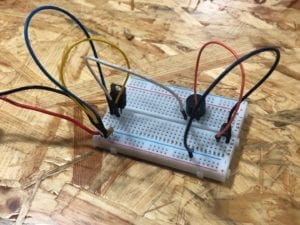
Photos:
Reflection:
As it is the first circuit we connect, we met a little bit more difficult to figure out how things work. But eventually, we figured out how the holes on the breadboard are connected. Another tricky thing is the approach to connect the switch into the circuit. With the help from one of the fellows, we found out that switch can be plugged into two sets of holes that are not connected so that the switch can actually realize its function as controlling whether there is electricity flowing in the circuit. During the process, we occasionally found that there was not enough space to put several connected appliances in the same set of holes. But we succeed in plugging them somewhere else and then use wires to connect them into the circuit. Another tip we got from the fellow is that, before finishing the circuit and checking there are no mistakes such as short circuit, the power should never be connected into the circuit.
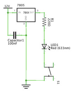
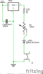
Circuit 2: Lamp
Components:
1 * 12-volt power supply: to provide the electrical power
1 * Breadboard: to provide a base for making electronic connections and aid in the prototyping of circuits.
1 * 100 nF (0.1uF) Capacitor: to store electricity while current is flowing into them, then release the energy when the incoming current is removed.
1 * LM7805 Voltage Regulator: to maintain a constant voltage level
1 * Push-Button Switch: a control mechanism which can be used to interrupt the flow of current through a circuit.
1 * LED: light up when there is electricity flowing in the circuit
1 * 220-ohm Resistor: resists the flow of electricity, and can be used to control the flow of current.
Several Jumper Cables (Hook-up Wires): to connect different components in the circuit
Diagram:
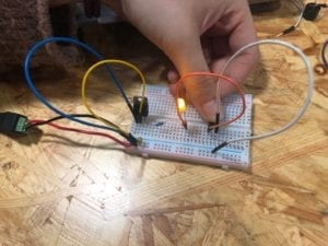
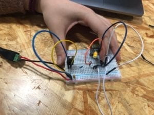
Photos:
Reflections:
With the experience of the first circuit, the second one seems to be much easier. The only problem we met is that we mistakenly connected the wires to the holes that are disconnected to the LED, meaning that the LED is not connected into the circuit at all. But by inspecting by ourselves we spotted the problem and fixed it. Therefore, we finished connecting this circuit rather smoothly with much difficulty, as we have had general experience of how to do so in the first circuit.
Circuit 3: Dimmable Lamp
Components:
1 * 12-volt power supply: to provide the electrical power
1 * Breadboard: to provide a base for making electronic connections and aid in the prototyping of circuits.
1 * 100 nF (0.1uF) Capacitor: to store electricity while current is flowing into them, then release the energy when the incoming current is removed.
1 * LM7805 Voltage Regulator: to maintain a constant voltage level
1 * Push-Button Switch: a control mechanism which can be used to interrupt the flow of current through a circuit.
1 * LED: light up when there is electricity flowing in the circuit
1 * 220-ohm Resistor: resists the flow of electricity, and can be used to control the flow of current.
1 * 10K ohm Variable Resistor (Potentiometer): a resistor with a sliding contact attached to a knob that outputs an adjustable voltage
Several Jumper Cables (Hook-up Wires): to connect different components in the circuit
Diagram:
Photos:
Reflection:
The third circuit is based on the second one. The only change we need to make is to insert a variable resistor into the circuit. The biggest problem we met here is that there was not enough space to do so. But according to our experience in the first circuit, we put the variable resistor in the right side of the breadboard and used wires to connect it into the circuit that mainly locates on the left side of the breadboard.
Question 1:
As far as I can think of, the switch, and the variable resistor both include interactivity. As is mentioned in the article “The Art of Interactive Design”, the interactive process includes input, process, and output. Our action to push the button on the switch or to adjust the resistance to change how light the LED is are the inputs. The circuits then process such inputs, meaning that electricity flow through the circuits built by us. Eventually, we are able to see the output of the process. For example, the buzzer makes sounds and the light of the LED changes. These all show us that the circuit we built is working as we expect them to, which is indeed a sort of interactivity.
Question 2:
From my perspective, interaction design and physical computing should be combined to create something that is controlled by people. The interaction design makes sure that human behaviors and actions are indispensable parts of interactive art. On the other hand, physical computing makes sure that the product is controllable in terms of human instructions or behaviors. That is, the process of physical computing provides interactive art the ability to change or adjust itself according to people’s instructions or behaviors. Only if a product or design contains both the elements, can it be called interactive art.