Materials:
1 * 42STH33-0404AC stepper motor
1 * L293D ic chip
1 * power jack
1 * 12 VDC power supply
1 * Arduino kit and its contents
2 * Laser-cut short arms
2 * Laser-cut long arms
1* Laser-cut motor holder
2 * 3D printed motor coupling
5 * Paper Fasteners
1 * Pen that fits the laser-cut mechanisms
Paper
Step 1: Build the circuit
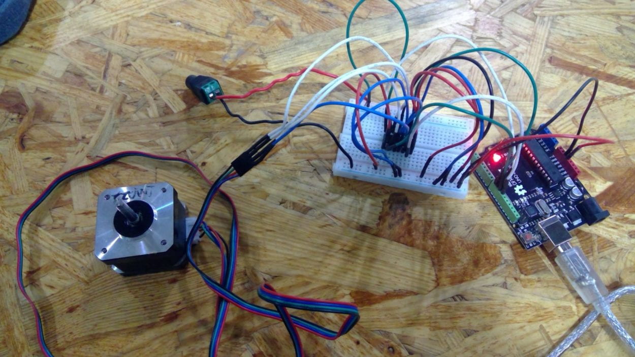
For step 1, I assembled everything according to the diagram in a minute because we’ve had so much experience in wiring up H-bridges. However, I have to admit that I never thoroughly figured out why the cables need to be connected this way. And although I have a blurred memory that we have talked about why the H-bridge controls the rotation direction in class, I am still not sure why it worked this way. So, I read through web pages and documents on the electronic parts, and I learned that a stepper motor functions following the change of electromagnetic signals. 
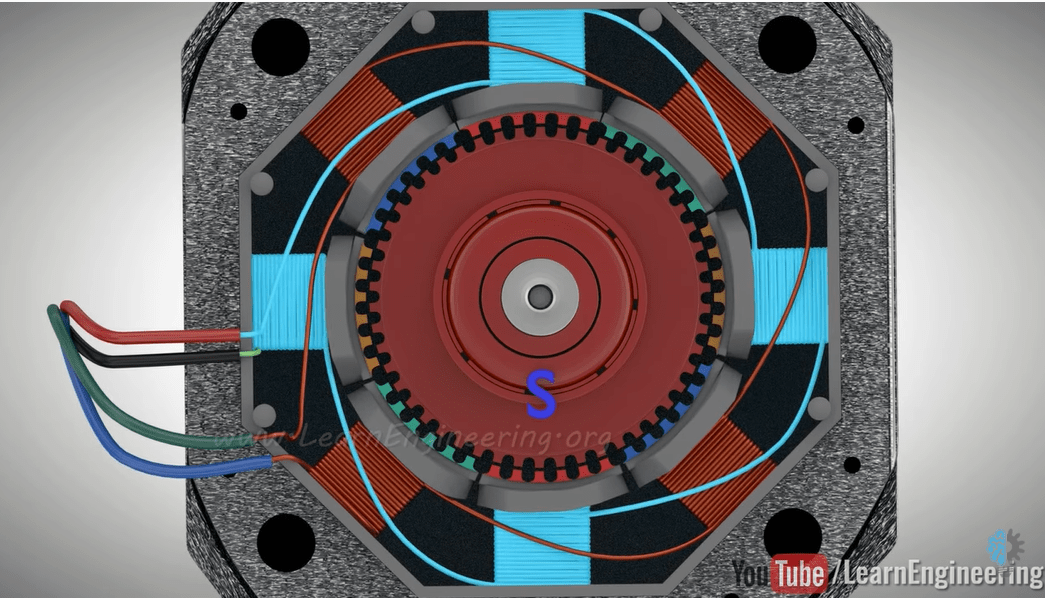
As shown in the picture above, electricity magnetizes set 1A and 2A, flowing through the red and black wires, and set 4A and 3A, flowing through the green and blue wires, in turn to attract or repulse the rotor and make it rotate. When electricity flows in the other direction, the rotation direction of the stepper will also change.
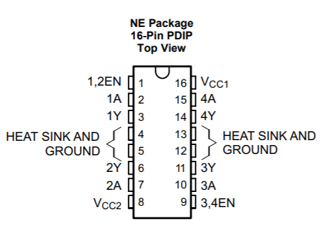
The turns between the sets are controlled by the H-bridge, giving high and low signals to pins 1-4A. And while we give 5V power to pins 1-4EN to activate pins 1-4A, electricity into V(CC1) is used to power the H-bridge itself, and that into V(CC2) is giving power to the stepper. That’s why we give different power to pins 1, 8, 9, 16 in the picture above, and the step motor has 4 wires attached to it.
After uploading the stepper code, the rotation direction is changing constantly.

Step 2: Control rotation with a potentiometer
If I want to control the angle of rotation based on the angle I turned the knob, I need to map the value returned by the potentiometer to the step of the stepper. Here is the revised code:
#include <Stepper.h>
#define STEPS 200
Stepper stepper(STEPS, 8, 9, 10, 11);
int previous = 0;

void setup() {
  stepper.setSpeed(30);
}

void loop() {
  int val = map(analogRead(0), 0, 1023, 0, 200);
  stepper.step(val - previous);
  previous = val;
}
Step 3: Build a Drawing Machine!
While I was assembling the machine, I found that the hands and the base are all laser-cut from the lab. I was amazed by how much the simple parts are capable of when they are properly organized and designed–with a basic stepper hooked on Arduino and the common paper clips, such an interactive device that draws out patterns is manufactured. I had great fun watching these two discs turning on my command and dragging the hands with them.
Documentation:
Question 1:
What kind of machines would you be interested in building? Add a reflection about the use of actuators, the digital manipulation of art, and the creative process to your blog post.
I am interested in building a machine that is pleasant to look at and fun at the same time. In the Papier project, not only are the patterns on the paper artistic, the device is also working perfectly as toys. Both of these two factors would make a machine cater to the need of its potential users aesthetically and pragmatically.
The actuators are the fundamental part of a machine if the designer intended to have the machine fulfill its job by moving. The more delicate the movement of an actuator, the better job the machine can accomplish. However, when I was reading the articles assigned for week five, it was unexpected for me to see that some small devices that involve using actuators are not electronic. A lot of toys takes energy when human touches or play with them. Also, a lot of Automata in the articles have the actuators exposing to the viewers. I always thought that putting the gears inside a device is a rule for machine designers because they are believed to be fragile and to mechanical to look at. When I think about it, I realized that they make much sense because when people watch the functioning of machines through its exposed inside organization, they can have a deeper understanding of the devices. And for children who play with these toys, it is also fun and inspiring when they see the parts moving to his movements.
Although in this recitation I built a machine that draws, I do not think that art in the future should be taken over by computers and artificial intelligence, because somehow I think that art or beauty is the deepest feeling of humanity, and should be exclusive to the naturally developed consciousness. However, I am not against using computers to assist the production of an idea because machines are tools for us and we better make the best use of them. For example, when an artist designs a sculpture, 3D printers can make the technique of carving materials not a limitation to him. Therefore, while an idea should be original, the process of realizing the idea can be assisted.
Question 2:
Choose an art installation mentioned in the reading ART + Science NOW, Stephen Wilson (Kinetics chapter). Post your thoughts about it and make a comparison with the work you did during this recitation. How do you think that the artist selected those specific actuators for his project?
The piece Fish, Plant, Rack created by Andy Gracie shows the communication between the three parties and how they help each other in surviving in a system. The fish in an aquarium sees the situation of the plant’s growth, and the robot reads its electric discharges to care for the plant. I think this design is brilliant because while it involves the aspect that computers are capable of and human beings are not, it also shows how machines can be integrated in the world of lives and help them live. When compared with what I’ve been doing in this recitation, I think the main difference is that while my device creates art in a random manner, Gracie’s device reads information from real life and brings a change to it. I really like his choice of actuators because in the photo, the robot seems to be moving smoothly in an environment filled with water. And I think the shape of the tube growing these plants has also made it harder for the actuators to move in between them.