In the first recitation, we tried soldering in person to take a peek at how circuits are connected together. Also, we built three circuits on a breadboard with detachable wires and parts in order to learn about how electricity and breadboards work. These exercises ware both a warm-up for this course and a foundation of working with Arduino boards.
Circuits
Materials:
- 1 * Breadboard
- 1 * LM7805 Voltage Regulator
- 1 * Buzzer
- 1 * Push-Button Switch
- 1 * Arcade Button
- 1 * 220 ohm Resistor
- 1 * 10K ohm Resistor
- 1 * 10K ohm Variable Resistor (Potentiometer)
- 1 * LED
- 1 * 100 nF (0.1uF) Capacitor
- 1 * 12 volt power supply
- 1 * Barrel Jack
- 1 * Multimeter
- Several Jumper Cables (Hook-up Wires)
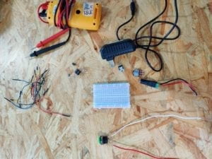
Below is a picture of all the materials:
Circuit 1: Door bell

Interestingly, the first exercise for me and my partner was the most difficult because neither of us understood how a breadboard works. At first, we connected power to one side of the board and ground to the other side, because I thought both sides would be the same. And we also put the electronic parts parallel with the rows that electricity flows through. We didn’t understand what was going on until the instructor explained to us that the lines are connected electronically and the two sides of the board are not connected at all. These are two of the most important takeaways from this recitation session.
This is how our final circuit looks like:
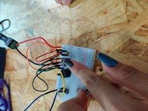
We struggled to make out the difference between the three feet of the transistor. When electricity is flowing through, the temperature on the transistor may be very high.
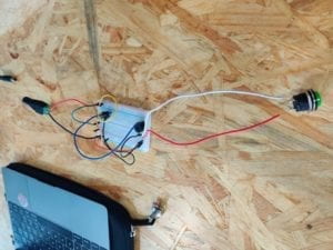
Circuit 2: Lamp

After understanding how circuits and breadboards work, building the second circuit became way easier for us. We used the button we made during soldering into the circuit to make switching it on and off easier. We don’t need to limit ourselves to the factory manufactured electronic parts. We can actually design and make parts tailored to our preference.
We didn’t really have time for the third circuit in class. But we talked through how to use a variable resistor in this diagram.
Reflections
After reading The Art of Interactive Design, in what way do you think that the circuits you built today include interactivity? Please explain your answer.
I think that the circuit respond to human’s switching and off immediately by its output devices. The three steps of the process of using these devices fit into the model of interactivity given by the author: the circuit first wait for the user to give an instruction of what to do and record the signals, the user gives his/her decision of whether to switch on or off, and finally, the circuit gets the instruction and executes it. However, according to the definition, I think a complete interactive product need to have more back and forth in these responses and the two parties’, and the expression of ideas and information should be more complicated than a simple on/off.
How can Interaction Design and Physical Computing be used to create Interactive Art? You can reference Zack Lieberman’s video or any other artist that you know .
In Zack Lieberman’s video, the device has a sensor attached on it to record the motion of human. And by computing and analyze the data gathered by these sensors, an output device can then perform another motion or give some feedback. In the case of eyewriter, the feedback would be the image generated by the software or the picture projected onto the building. Art can be created this way in a sense that either interaction design and physical computing use technology to help human create art in the traditional forms, or their output itself represent a new type of art.