Lab Date: Feb. 15, 2019
Instructor: Marcela
Lab Partner: Ivy
Aim of Today’s Lab: Learn how to solder an arcade button and complete three circuits using a breadboard.
Soldering arcade button
Process:
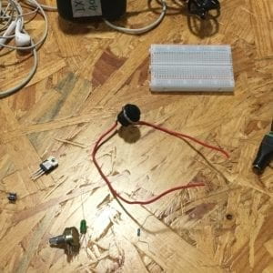
In this exercise, we soldered an arcade button. We soldered two jumper cables to our button by melting a metal wire to our cables. We also used pilers to expose some of the copper to help us solder the metal to the cable.
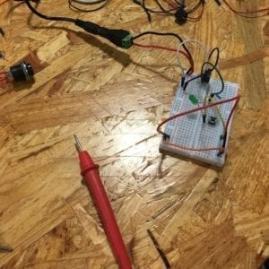
Circuit 1: Door Bell
Materials used:
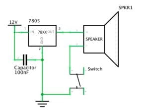
Breadboard, Speaker/Buzzer, Capacitor, Push-Button Switch, LM7805 Voltage Regulator, 12 volt Power Supply, Barrel Jack, Jumper Cables
Process:
I was pretty intimidated beginning this exercise as my partner and I had no experience and didn’t know where to begin, so we began by asking fellows a lot of questions the breadboard, how to use it, and about some of the materials we acquired in the exercise. After assembling the circuit by ourselves according to the schematic, we ran into some problems. Consulting several fellows, we found out our capacitor was in the wrong place so we moved it next to our jumper cables in the power rails. We also found out that our voltage regulator was in the incorrect order so we fixed the jumper cables into the correct order. After fixing these issues, our circuit worked.
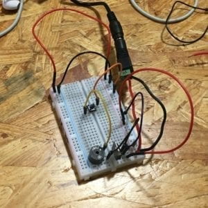
With Arcade Button
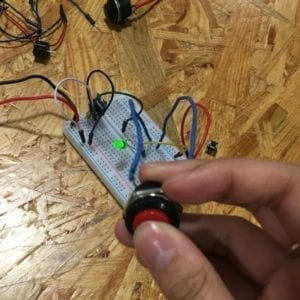
Circuit 2: Lamp
Materials used:
Breadboard, LED, 220 ohm Resistor, Capacitor, Push-Button Switch, LM7805 Voltage Regulator, 12 volt Power Supply, Barrel Jack, Jumper Cables

Process:
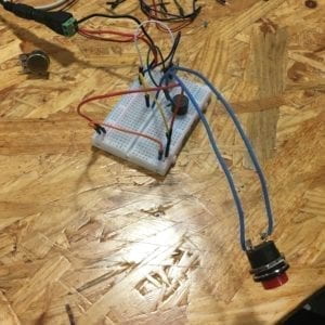
There was not much change between the door bell circuit and the lamp circuit. For this circuit, we exchanged the speaker/buzzer for the LED and 220 ohm resistor and rearranged the position of our capacitor and jumper wires. We tested both resistors by using the multimeter to determine which was the resistor we needed. There wasn’t much trouble building this circuit. However, we realized when building this circuit that we needed to exchange our push-button switch with the arcade button we had soldered from earlier. Although when we tried our arcade button, the LED failed to turn on. After consulting a fellow, we exchanged our arcade button with another one as the wires to our buttons were suspected to be burnt when we were soldering. We also learned how a push button worked and how to place it in our breadboard despite the fact our guesses on how to use it were correct. Our circuit worked again.
With Arcade Button
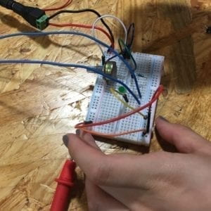
Circuit 3: Dimmable Lamp
Materials used:
Breadboard, LED, 220 ohm Resistor, 10K ohm Variable Resistor, Capacitor, Push-Button Switch, LM7805 Voltage Regulator, 12 volt Power Supply, Barrel Jack, Jumper Cables

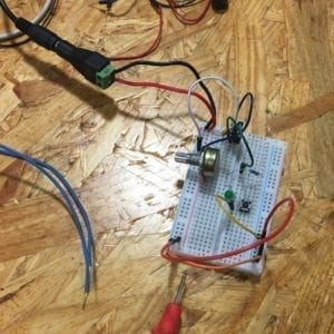
Process:
There was not much issue with this circuit. We added the 10K ohm variable resistor and rearranged the position of our jumper wires. Tested the circuit with both buttons and it worked perfectly! We returned to our door bell circuit and tried it with the arcade button as well.
With Arcade Button
Conclusion
I learned so much during this recitation: what a breadboard does, how to use it, how it works, and how to read schematic diagrams and build simple circuits like the ones we did. Without prior experience, it also confirmed by beliefs that if you don’t know something, there are always resources out there to help you and questions to ask. Some mistakes we had during this exercise was understanding how certain components worked (capacitor, voltage regulator, buttons) and how to implement it into our circuits. We also learned some other tips such as using two different colored wires for our arcade button to tell the difference between our ground and power connections. All in all, this exercise made me excited for what’s to come in this class.
Answers to Questions
After reading The Art of Interactive Design, in what way do you think that the circuits you built today include interactivity?
The Art of Interactive Design describes interactivity as at least two purposeful actors that react to one another. After reading this article, the circuits we built in this recitation in my opinion include interactivity because we can interact with it and it will respond to our actions. With the doorbell and lamp circuit, we could press a button which emitted a sound or turned an LED light on and allow these reactions to turn off when we release the button. With the dimmable lamp, we could not only press and release a button which to turn on and off the light, but we could also change the brightness of the LED light.
How can Interaction Design and Physical Computing be used to create Interactive Art? You can reference Zack Lieberman’s video or any other artist that you know.
Interactive Design and Physical Computing can be used to create Interactive Art in all kinds of ways. One example of Interactive Art using Interactive Design and Physical Computing is Dialect for a New Era by Frederik Duerinck and Marcel Van Brakel which I experienced in the Cooper Hewitt last summer. This work of art uses Interactive Design by allowing the user to press a button on a glowing square pillar which in turn emits a scent allowing the user to smell. It uses Physical Computing through the button as well. The button is the input and in turn the piece understands to output a smell through holes above the button.