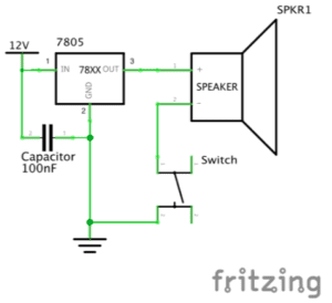
Circuit 1: Door Bell
Components:
1 * Breadboard – This is the base for us to connect all the other electrical components together without soldering. There are also connections within the breadboard that we can make use of.
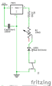
1 * LM7805 Voltage Regulator – To make sure that the current went into the circuit is smooth, we need a voltage regulator so that the buzzer would work. Also, may work with the capacitor to protect other components (LED, buzzer) if there is a sudden blackout.
1 * Buzzer – This component can make sound if connected to electricity. Shall be viewed as the central component of a door bell.
1 * Push-Button Switch/ 1 * Arcade Button – They are two different kinds of switches that can control whether there is electricity in the circuit.
1 * 100 nF (0.1uF) Capacitor – In this circuit, it is the same as a resistor that has an infinite amount of resistance so as the voltage regulator could be connected to ground. Also, the electricity stored in the capacitor may help to protect the LED or buzzer if there is a sudden blackout.
1 * 12 volt power supply – get power from the socket.
1 * Barrel Jack – connect the whole breadboard with the 12v power supply.
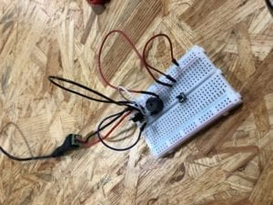
Pictures of the Circuit:
Process:
It is always very difficult to start doing something that I am unfamiliar with. In fact, I have never seen breadboards and never finished a circuit like this before. At the very beginning, my partner and I even thought that we did not need to use electric wires if we put everything on a breadboard since there are built-in connections. However, we immediately realized it was a mistake. After getting more wires, we stuck on the installation of the voltage regulator and capacitor. We tried to connect them via wires but it turned out that we could use the built-in circuit inside the breadboard. To tell the truth this is confusing because we were unsure how to make use of the connection within the breadboard. The next difficulty we faced is the switch. It was really hard to understand why the switch has four pins instead of two before Nick introduced the design of the switch. Anyways, after encountering so many problems, our circuit finally worked and the process of changing the switch into an arcade button went on smoothly since we have already got some sense of building a circuit.
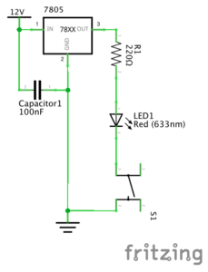
Circuit 2: Lamp
1 * Breadboard – This is the base for us to connect all other electrical components together without soldering. There are also connections within the breadboard that we can make use of.
1 * LM7805 Voltage Regulator – To make sure that the current that went into the circuit is smooth so that the LED would work. Also, may work with the capacitor to protect other components (LED, buzzer) if there is a sudden blackout.
1 * Push-Button Switch – control whether there is electricity in the circuit.
1 * 100 nF (0.1uF) Capacitor – In this circuit, it is the same as a resistor that has an infinite amount of resistance so as the voltage regulator could be connected to ground. Also, the electricity stored in the capacitor may help to protect the LED or buzzer if there is a sudden blackout.
1 * 12 volt power supply – get power from the socket.
1 * Barrel Jack – connect the whole breadboard with the 12v power supply
1 * 220 ohm Resistor – To reduce the voltage connected to the LED and avoid damage.
1 * LED – give out light after electricity flows into the circuit.
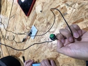
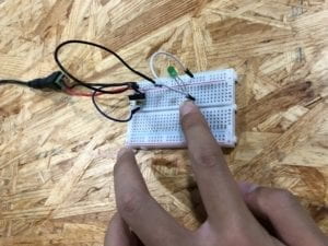
Pictures of the Circuit (My index finger is where the switch was at):
Process:
The process of building a lamp is much easier because we have already built the foundation when building the first circuit. We just need to change the buzzer into a LED light. However, it is important to notice that the positive and negative poles of the LED. The longer pin represents the positive pole and we need to follow the right direction to successfully light it up.
Circuit 3: Dimmable Lamp
1 * Breadboard – This is the base for us to connect all other electrical components together without soldering. There are also connections within the breadboard that we can make use of.
1 * LM7805 Voltage Regulator – To make sure that the current that went into the circuit is smooth so that the LED would work. Also, may work with the capacitor to protect other components (LED, buzzer) if there is a sudden blackout.
1 * Push-Button Switch – control whether there is electricity in the circuit.
1 * 100 nF (0.1uF) Capacitor – In this circuit, it is the same as a resistor that has an infinite amount of resistance so as the voltage regulator could be connected to ground. Also, the electricity stored in the capacitor may help to protect the LED or buzzer if there is a sudden blackout.
1 * 12 volt power supply – get power from the socket.
1 * Barrel Jack – connect the whole breadboard with the 12v power supply
1 * 10K ohm Variable Resistor (Potentiometer) – This resistor allow us to adjust the resistance so as to control the lightness of the LED.
1 * LED – give out light after electricity flows into the circuit.
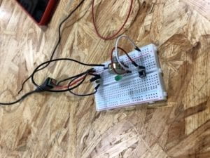
Pictures of the Circuit:
Process:
To convert circuit 2 into circuit 3, we only need to change the resistor into a potentiometer. But initially I did not know why the potentiometer has three pins. I happened to connect the two pins that are seprarated from each other into the circuit and the LED was not on. Later, after receiving some instructions, I found out that I should connect to the two pins on the left and in the middle. In that case, when I rotate the potentiometer, the lightness of LED would change.
Answer for Reflection Question 1:
According to the author, we should define interactivity as “a cyclic process in which two actors alternately listen, think, and speak.” From my perspective, the interactivity of the circuit we built comes from its response when we press the switches. When we implement such an action, the circuit receives a signal. In other words, this is what it could ‘hear’ from human beings. We could hardly say that there is a process of ‘thinking’ within the circuit but after it receives the signal, it answers by turning on the whole circuit and lighting up the LED. I regard this as a way for it to ‘speak’ with us. I think this entire process has met the author’s criteria for interactivity. What is more, for green hands like us to build a circuit often needs communication with others. It would be unlikely for us to complete a circuit solely from the materials on our table. When we have conversations with others about our thoughts on the circuit, this includes interactivity as well. So, I think the circuit itself and the process of building includes two different levels of interactivity but they are both inspiring.
Answer for Reflection Question 2:
In my opinion, there are two ways that physical computing and interaction design can be used to create interactive art. One method is to use physical computing to expand the existing forms of art so that we could see artworks that we would not be able to. An example for this is ‘The Eyewriter.’ The engineers created a method that could help an artist who could not move his body to continue creating graffitis. In terms of art, the work we see is essentially graffiti but the production process involved the intelligence of interaction design and physical computing. Another way that interaction design and physical computing can creat interactive art is to come up with completely different forms of art such as the ‘wood mirror’ that could capture people’s movements by changing colors. Without the help of technology, even if artists have the materials to present the idea, the visual effect and artistic value would not be as good as the one we saw in the film clip. In other words, physical computing helps many artists to put their imagination into reality to the best extent and help them better express their ideas.