Recitation Week 1
Materials
Breadboard:a layout of conduc
tive terminals that provides a consistent cable design for t
he construction of circuits
LM7805 Voltage Regulator:maintains a constant voltage level so the buzzer and LED can operate efficiently
Buzzer:an electrical device that makes a buzzing noise
Push-Button Switch:gives the interactor the power to choose when to let the current flow
Arcade Button:allows one to control whether or not electricity passes through the circuit by pressing the button
220 ohm Resistor:adds resistance to the circuit in order to decrease the voltage and keep the LED stable
LED:a semiconductor diode which glows when a voltage is applied
100 nF (0.1uF) Capacitor:stores energy in the form of an electrostatic field between its plates
10K ohm Variable Resistor (Potentiometer):a resistor with an adjustable voltage divider
12 Volt Power Supply:used to reduce the mains electricity at 240 volts AC down to 12 volts do make it more useable
Barrel Jack:a power connector used for connecting low-voltage devices to external electricity
Multimeter:measures electric current, voltage, and usually resistance
Jumper Cables (Hook-up Wires):a single insulated conductor used for low-voltage applications
Circuit 1:
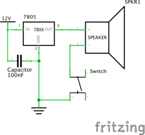
Building Process
Building the first circuit was somewhat difficult, as we had to learn how to work with the layout of the breadboard and all our materials. We encountered the problem that we couldn’t identify which piece was which but were able to refer to the recitation notes to see a picture and function of each piece. Once we identified all the pieces and placed them in the correct circuit, we tried hitting the button, but failed to make the buzzer buzz. After receiving help from one of the teaching fellows, we realized one of our pieces was faulty, and replaced it with a new one. Upon this adjustment, the buzzer worked, and we were able to take apart the circuit and start the next one.
Circuit 2:
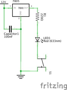
Building Process
The process of building the second circuit went a lot smoother than the first, as we were more familiar with the materials and working with the breadboard. The only difference between circuit 1 and 2 is that we replaced with an LED light and added a resistor to tone down the voltage of the bulb. Because of this, we were able to reuse a lot of the previous circuit and did not run into issues while completing it.
Circuit 3:
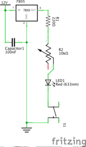
Building Process
Building the last circuit went faster than building the other 2, although we did run into issues along the way. We did not understand the circuit diagram at first and were unable to place the pieces correctly into the circuit. Though circuit 3 was harder for us to complete than circuit 2, it was easier than circuit 1. All we had to do to complete this circuit was add the 10K ohm Variable Resistor to circuit 2 to be able to adjust the brightness of the bulb. At first, the LED would not turn on, so we once again asked a teaching fellow to assist with our issue. He then checked all parts of our circuit and it seemed to be correct, so we deduced that the problem lied in the reliability of the materials we used.
Question 1:
The circuits we built include interactivity because all parts of the circuit have to work together in order for it to perform the desired result. For example, in the third circuit, the resistor works with the capacitator and current flowing through the breadbox to make the LED work and stay stable. While the resistor dissipates energy, the capacitator stores it, which allows the circuit to function as desired and turn on either the buzzer or the LED when the button is pressed. By using wires and other materials that facilitate or alter the flow of energy, electrically charged particles can be passed on from unit to the next, thus having the components of a circuit working together towards a common purpose.
Question 2:
Physical computing can be used to “bring art to life”, as in the project shown by Zack Lieberman. It can be used to trick the eye into making otherwise lifeless or still images move and respond to cues triggered by the art’s audience, like in exhibitions in art museums that allow visitors to interact with and create their own art. Digitalizing art allows for a wide range of interactive possibilities, as coding allows for limitless possibilities for the creation of such artworks. Computing can allow artists to create things that would otherwise be physically impossible, such as drawing and projecting graffiti live onto a road using eye-tracking technology (shown in Liebermann’s video).